128
POSITION
ON THE IMAGE
WRITING
NEXT TO LED
RELATIVE
TO
1
VAP Compressor
2
SH
Static relay
3
+12V
Power supply +12VDC
4
+5V Power supply +5VDC
5
+3V3 Power supply +3.3VDC
6
LEV Tank level
VOL Flowmeter
PF-GR Filter holder presence sensor
7
GR Coffee group’s heating element
CH Coffee boiler’s heating element
8
TANICA Tank valve
H2O-STOP Water stop valve
PULSEJET None
PUMP Pump
AIR-VAP Easycream air valve
EVVAP Steam valve
ON-OFF Contactor
AUTOLIV Self-levelling valve
H2O-THE Hot and cold water valves
EV-GR Coffee valve
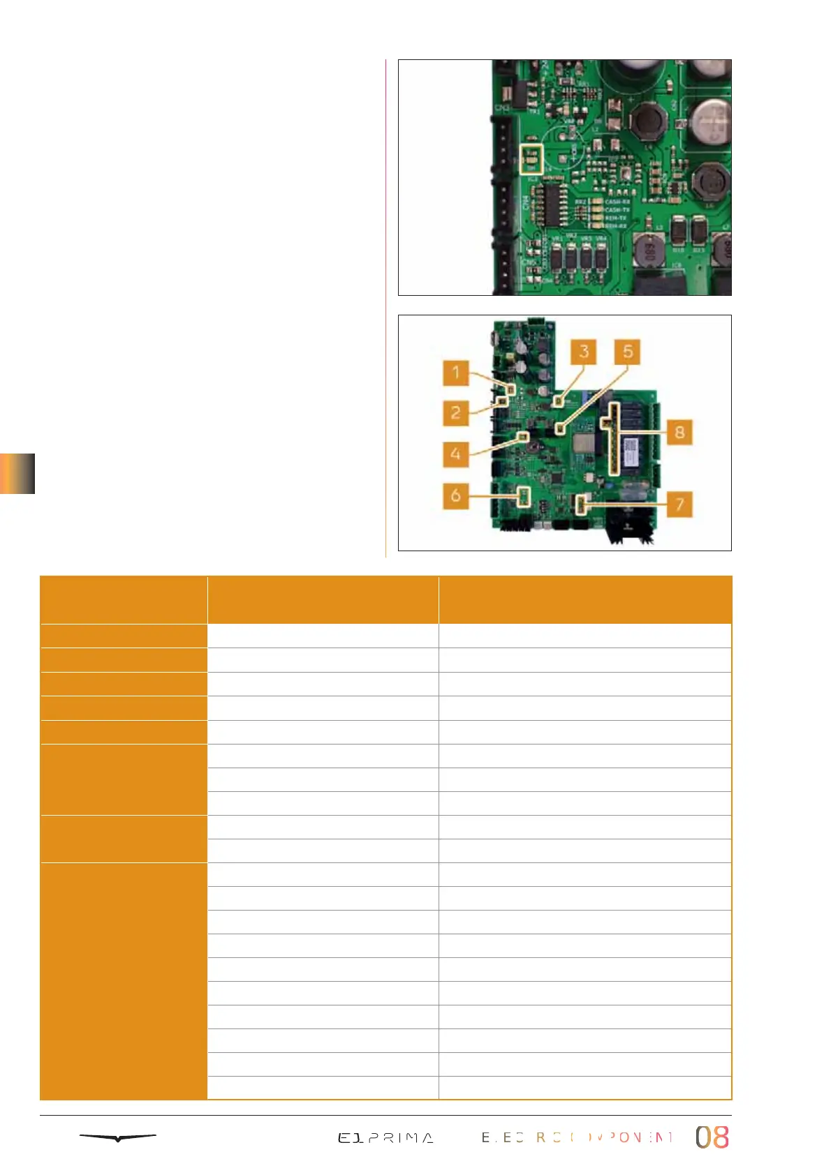
8.1.1 CONTROL UNIT LEDS
The control unit contains LEDs, useful to
recognize the functioning of parts of the
machine.
There is a writing next to each LED to indi-
cate what it refers to. For example, the focus
on the picture shows the writing SH, that
indicates the activation of the static relay.
Every LED can have a different meaning,
based on the part it refers to. It can mean
for example: that function is fine, or the con-
trol unit is turning ON that part, or the con-
trol unit is receiving signal from that part.
The most useful LEDs are:
16
15
 Loading...