FUEL SYSTEM / FUEL INJECTION
5.25
5
© Copyright 2012 Polaris Sales Inc.
9924047 - 2012-2013
VICTORY Cross Roads / Cross Country Service Manual
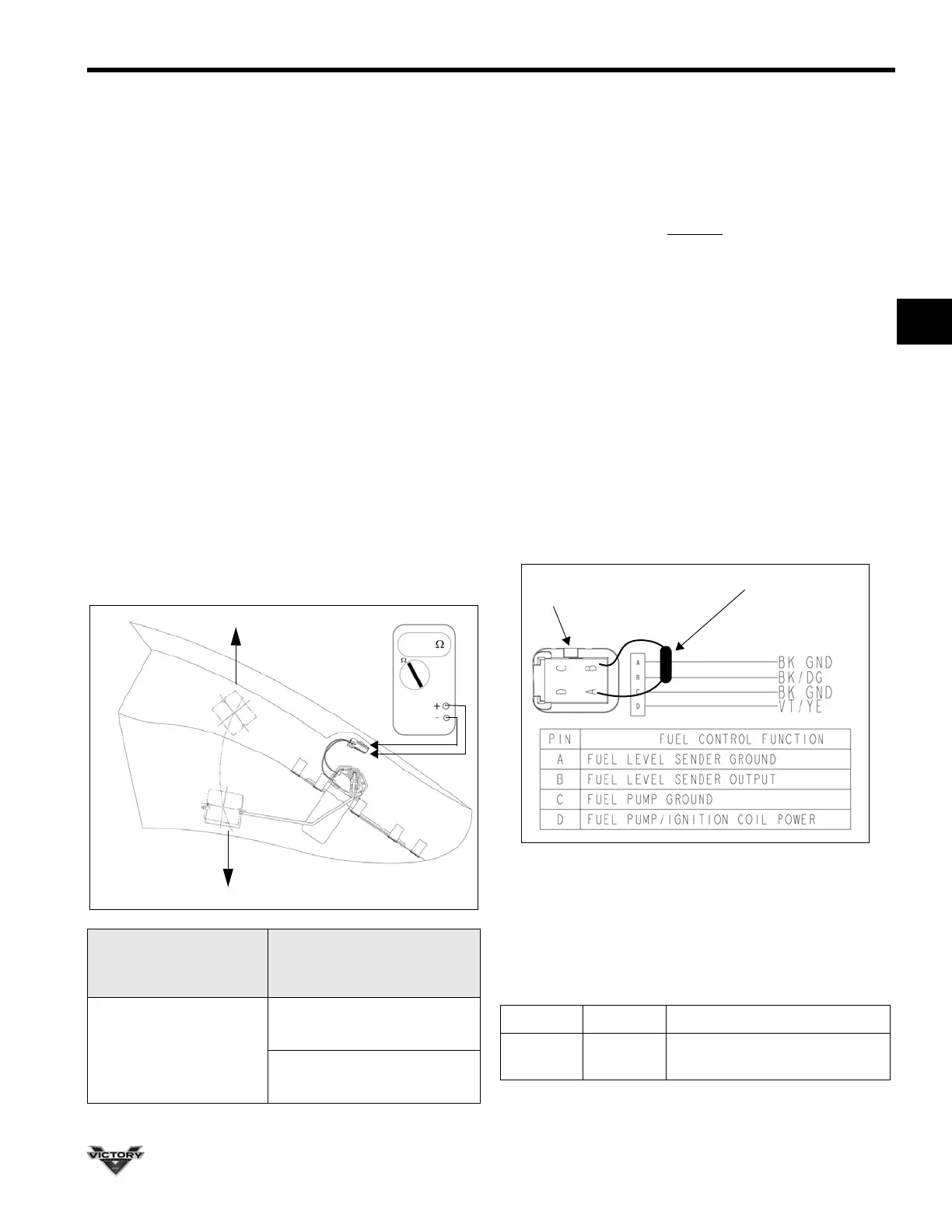
Fuel Level Sensor Resistance Test
OVERVIEW OF OPERATION: The fuel level sensor is a
mechanical float arm located inside the fuel tank. Circuit
resistance determines the reading on the fuel level gauge
(Cross Country) or on the fuel level bar display on the
speedometer (Cross Roads). When the fuel level
indicated on the fuel gauge is below 1/4 tank, a LOW
FUEL warning icon lights up on the information display
(Cross Country).
Follow the steps below to test the sensor circuit with an
ohmmeter.
1. Remove side covers and seat (Chapter 3).
2. Disconnect vent and water drain hoses at rear of tank.
3. Remove rear tank mounting bolts.
4. Lift and support rear of fuel tank high enough to access
fuel level sensor / fuel pump connector.
5. Disconnect the harness.
6. Set multimeter to measure resistance.
7. Attach meter leads to pin A and pin B of 4-pin connector
out of the fuel pump. Estimate the fuel level in the tank
and compare resistance reading to the table below.
Fuel Level Sensor Bypass Test
1. If fuel gauge is inoperative but level sensor resistance
is correct, perform the following test when the
connector is still unplugged.
2. Connect a 50 Ohm (minimum) resistor across Pin A
and Pin B on the harness
side of the fuel pump
connector (connect Black/Dark Green wire to Black
wire).
3. Turn ignition key ON and engine stop switch to RUN.
4. The fuel gauge should indicate between FULL and
empty depending on the resistor value used for testing.
NOTE: At least 50 Ohms should be installed in series
with Pins A and B. Connecting Pin B directly to Pin A
or to chassis ground will set an error code.
5. If gauge does not function, check continuity of Black
wire (Pin A) to ground. Resistance should be less than
.5 Ohms. If ground is OK, check all pin connections in
the fuel pump connector and the gauge connector (in
headlamp or fairing) and verify good continuity of BK/
DG wire to the gauge connector.
Error Message (Cross Roads)
If the fuel level sensor is disconnected, an error message
will be displayed on the speedometer information screen.
Resistance Measured
From Pin A to Pin B in
4-Pin Connector
Approximate
Resistance
Sensor Resistance
(Room Temperature)
FULL (Sensor Arm Up)
50
+/- 3
EMPTY (Sensor Arm Down)
250
+/- 5
Message Screen Indicates
ERROR Fuel Level
Fuel sensor disconnected /
shorted
Fuel Pump Connector
50-250 Ohm resistor
(harness side)
 Loading...