Do you have a question about the Victron energy Digital Multi Control 200/200A and is the answer not in the manual?
Lists compatible inverter/charger models for the control panel.
Basic setup instructions for connecting the control panel.
Details the contents included in the product package.
Explains how the panel integrates with different system configurations.
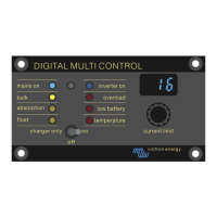
Functionality of the switch for turning the system on/off.
Explanation of the status indicator LEDs on the panel.
Information provided by the 7-segment display.
How to adjust the AC input current limit using the knob.
How the panel adapts to systems with multiple AC inputs.
Integration with generators via external transfer switches.
Setup for a MultiPlus system with a single AC source.
Setup for a Quattro system with two AC sources.
Setup for a MultiPlus system using an external transfer switch.
Setup for a MultiPlus system with multiple AC sources.
Instructions for physically mounting the control panel.
How to connect the control panel to the inverter/charger.
How to connect the control panel to an external transfer switch.
Describes how to enter and navigate the setup menu.
Parameter for aligning AC current in pre-VE.Bus systems.
Setting the AC current limit for generator input.
Setting upper limits for AC inputs to prevent overcurrent.
How remote settings affect the AC input current limit.
Provides examples for setting configuration parameters.
How to use the control panel's switch for system power.
Detailed steps for using the knob to set the AC current limit.
Explanation of automatic adjustment of LED brightness.
Illustrative examples for pre-VE.Bus systems with AC sources.
General configuration steps for pre-VE.Bus systems.
| Model | Digital Multi Control 200/200A |
|---|---|
| Current Rating | 200A |
| Communication | VE.Net |
| DC Input Current | 200A |
| VE.Net Interface | Yes |
| Display | LCD |
| Voltage | 12V / 24V |
| DC Input Voltage | 8-70V |
| Operating Temperature | -20°C to +50°C |
| Protection | Reverse polarity |