Recommended cable lugs
Size
AWG 2/0 Molex part no. 19221-0243
AWG 2 Molex part no. 19221-0233
* Follow local installation rules.
** Do not locate battery cables in a closed conduit
*** “2x” means two positive and two negative cables.
Remark: Internal resistance is the important factor when working with low capacity batteries. Please consult your supplier or the
relevant sections of our book ‘Energy Unlimited’, downloadable from our website.
Procedure
Proceed as follows to connect the battery cables:
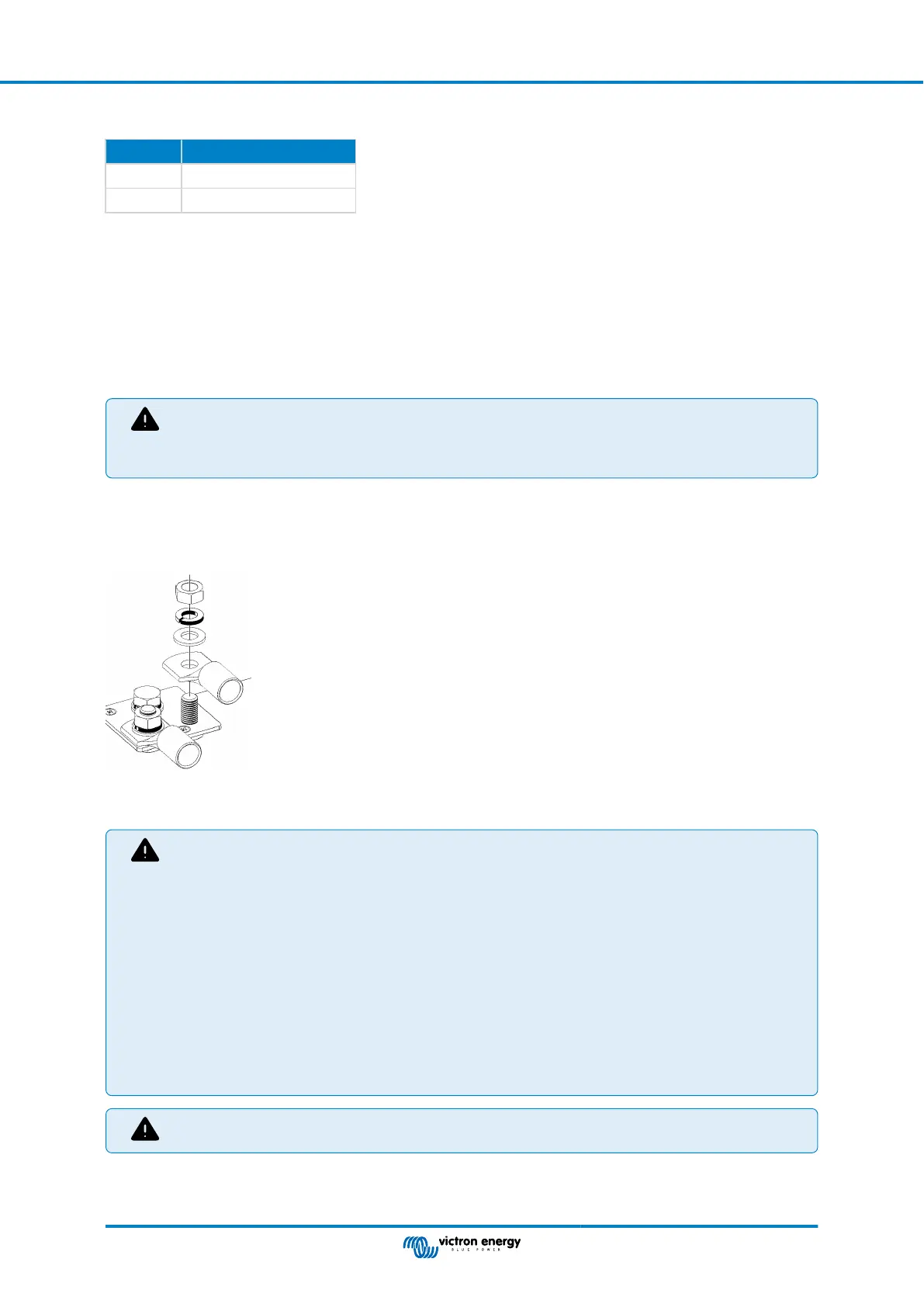
Use a torque wrench with an insulated box spanner in order to avoid shorting the battery.
Recommended torque: 12 Nm (M8 nut)
Avoid shorting the battery cables.
• Undo the two screws at the bottom of the enclosure and remove the service panel
•
Connect the battery cables: see Appendix A
• Tighten the nuts well for minimal contact resistance.
• The connector goes on first, then the flat washer, lock washer and nut. Tighten the nuts well for minimal contact resistance.
4.3. Connection of the AC cabling
The MultiPlus-II is a safety class I product (supplied with a ground terminal for safety purposes). Its AC input
and/or output terminals and/or grounding point on the outside of the product must be provided with
an uninterruptible grounding point for safety purposes.
The MultiPlus-II is provided with a ground relay (relay H, see appendix B) that automatically connects the
Neutral output to the chassis if no external AC supply is available. If an external AC supply is provided,
the ground relay H will open before the input safety relay closes. This ensures the correct operation of an
earth leakage circuit breaker that is connected to the output.
• In a fixed installation, an uninterruptable grounding can be secured by means of the grounding wire of the
AC input. Otherwise the casing must be grounded.
• In a mobile installation (for example, with a shore current plug), interrupting the shore connection will
simultaneously disconnect the grounding connection. In that case, the casing must be connected to the
chassis (of the vehicle) or to the hull or grounding plate (of the boat).
In case of a boat, direct connection to the shore ground is not recommended because of potential galvanic
corrosion. The solution to this is using an isolation transformer.
This unit or system is provided with fixed trip limits and shall not be aggregated above 30 kw on a single point
of common connection.
A blade tool of 2.5mm (e.g. a screwdriver) is required to operate the spring loaded AC terminal blocks.
The terminal blocks can be found on the printed circuit board, see Appendix A.
MultiPlus-II 48V 3kVA 120V
Page 12 Installation
 Loading...