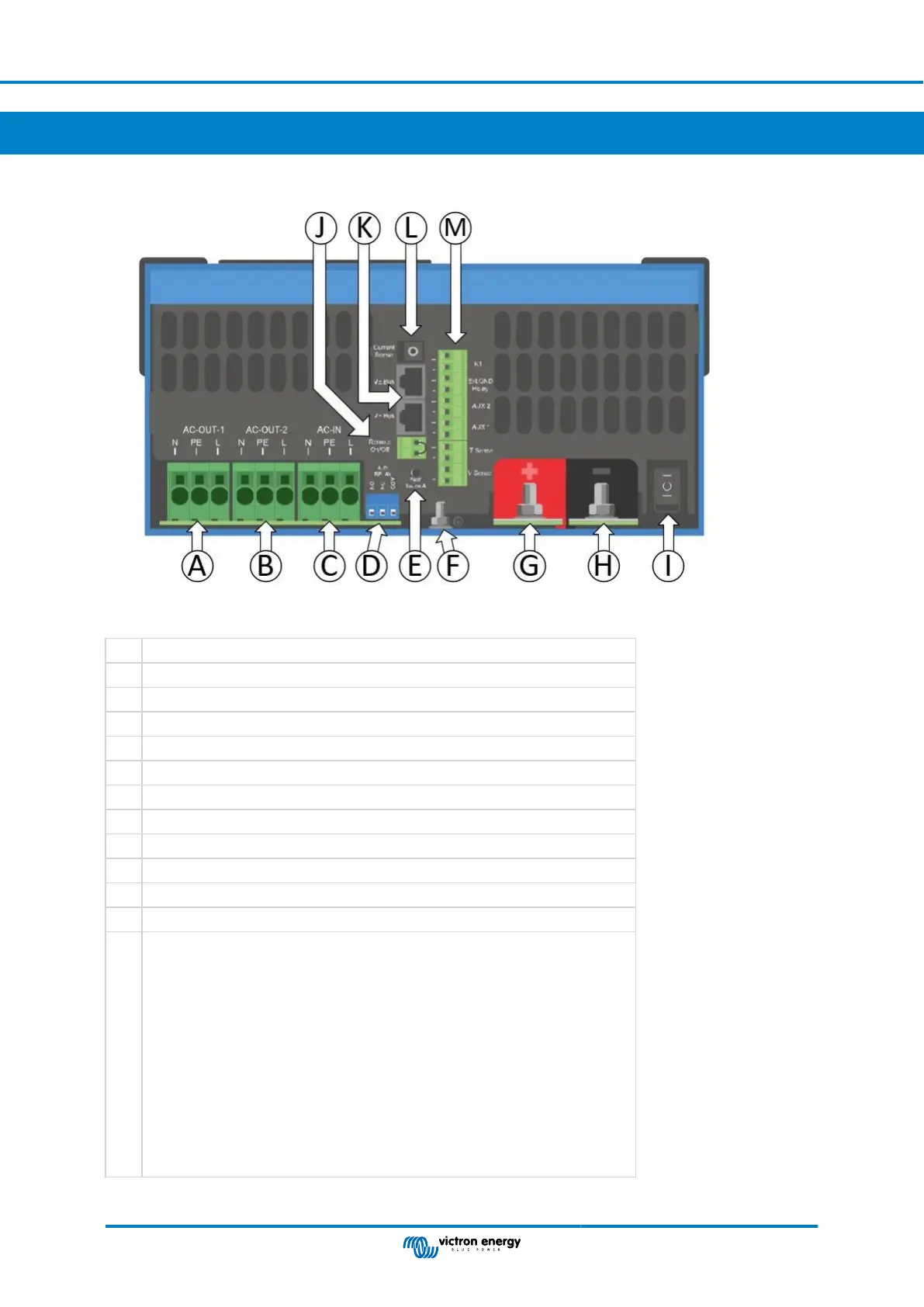
Appendix A. APPENDIX A: Connection overview
A Load connection. AC out1. Left to right: N (neutral), PE (earth/ground), L (phase)
B Load connection. AC out2. Left to right: N (neutral), PE (earth/ground), L (phase)
C AC input: Left to right: N (neutral), PE (earth/ground), L (phase)
D Alarm contact: (left to right) NO, NC, COM.
E Push button A – To perform a startup without assistants.
F Primary ground connection M6 (PE).
G M8 battery positive connection.
H M8 battery minus connection.
I switch: 1=On, 0=Off, ||=charger only
J Connector for remote switch: Short to switch “on”.
K 2x RJ45 VE-BUS connector for remote control and/or parallel / three-phase operation
L External current sensor
M Terminal for: top to bottom:
1. 12V 100mA
2. Programmable contact K1 open collector 70V 100mA
3. External ground relay +
4. External ground relay –
5. Aux input 1 +
6. Aux input 1 –
7. Aux input 2 +
8. Aux input 2 –
9. Temperature sense +
10. Temperature sense –
11. Battery voltage sense +
12. Battery voltage sense -
MultiPlus-II 48V 3kVA 120V
Page 27 APPENDIX A: Connection overview
 Loading...