This product may only be installed by a qualified electrical engineer.
2.1 Location
The product must be installed in a dry and well-ventilated area, as close as possible to the batteries. There should be a clear space of at
least 10cm around the appliance for cooling.
Excessively high ambient temperature will result in the following:
• Reduced service life.
• Reduced charging current.
• Reduced peak capacity, or shutdown of the inverter.
• Never position the appliance directly above the batteries.
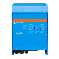
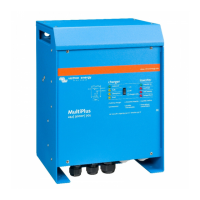
The MultiPlus is suitable for wall mounting. For mounting purposes, a hook and two holes are provided at the back of the casing (see
appendix G). The device can be fitted either horizontally or vertically. For optimal cooling, vertical fitting is preferred.
The interior of the product must remain accessible after installation.
Try and keep the distance between the product and the battery to a minimum in order to minimize cable voltage loss.
For safety purposes, this product should be installed in a heat-resistant
environment. You should prevent the presence of e.g. chemicals, synthetic
components, curtains or other textiles, etc., in the immediate vicinity.
Each system requires a method of disconnecting the AC and DC circuits. If the
overcurrent protection device is a circuit breaker, it will also serve as the
disconnect. If fuses are used, separate disconnect switches will be needed
between the source and the fuses.
To reduce the risk of fire, do not connect to an ac load center (circuit breaker
panel) having multiwire branch circuits connected.
2.2 Connection of battery cables
In order to utilize the full capacity of the product, batteries with sufficient capacity and battery cables with sufficient cross section should
be used. The DC cables must be copper and rated 90ºC (194ºF) See table.
12/3000/120 24/3000/70
Recommended battery capacity (Ah)
Recommended cross section (per +
and - connection terminal)
2x AWG 1/0 AWG 1/0
‘2x’ means two positive and two negative cables.
Recommended cable lugs
Molex part no. 19221-0240
Molex part no. 19221-0233
Remark: Internal resistance is the important factor when working with low capacity batteries. Please consult your supplier or the relevant
sections of our book “Energy Unlimited”, downloadable from our website.
Procedure
Proceed as follows to connect the battery cables:
 Loading...