PAGE 6 of 32 DIGITAL GSM INTERCOM TECHNICAL MANUAL VER2.1.1
SYSTEM COMPONENTS
A system comprises of an intercom panel, power supply, SIM card and antenna. The
intercom panel is of modular design allowing it to be customised to the installation
requirements by including proximity access control, coded access or bioaccess.
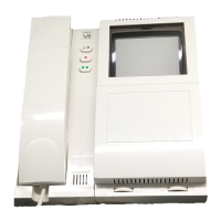
DIGITAL MODULE
The digital panel is available for the 4000 Series modular design or flush vandal resistant.
There are two versions in the 4000 series design, name scroll facility which includes a
numeric keypad and 3 buttons to navigate tenants/company names on the display and a
alpha numeric version which includes a numeric keypad and letters A-F. The vandal
resistant panel is also available with letters A-I.
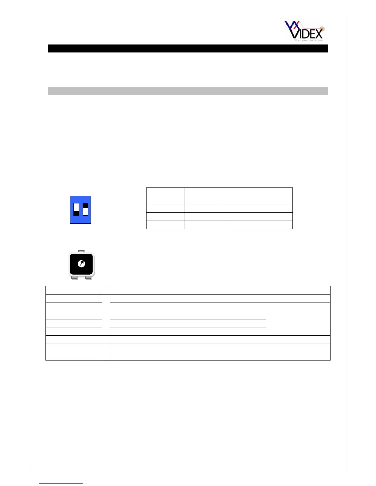
DIP SWITCH SETTINGS
There are 2 dip-switches located on the back of the module. They can be used to alter the
volume from the Door Intercom speaker. Additionally, the volume can also be adjusted
during a call via the telephone keypad.
SPEAKER VOLUME
LCD DISPLAY CONTRAST
CONNECTION DESCRIPTION
+12V 12Vdc – 14Vdc input
0V Ground connection
C Common connection of dry contact relay
NO Normally open connection of dry contact relay
NC Normally closed connection of dry contact relay
AO Auxiliary output switched 0V (Open collector output)
PTE Exit button input switched 0V (0V to trigger)
AI Auxiliary input switched 0V (0V to trigger, triggers AO)
ANTENNA
The GSM antenna connects to the SMA female bulkhead on the rear of the module. A
GSM antenna with a SMA male connector should be used.
Note: An antenna must always be connected and positioned vertically.
Note: Always route the GSM cable away from the microphone wires and the power
supply wires to avoid interference on the speech channels.
1 2 GAIN (dB)
ON ON 6
ON OFF 12
OFF ON 18
OFF OFF 23.5
ON
1 2
Relay contacts:
3A@24Vdc
3A@120Vac
Adjust the LCD contrast by turning the pot on the
rear of the panel next to the terminal connector.