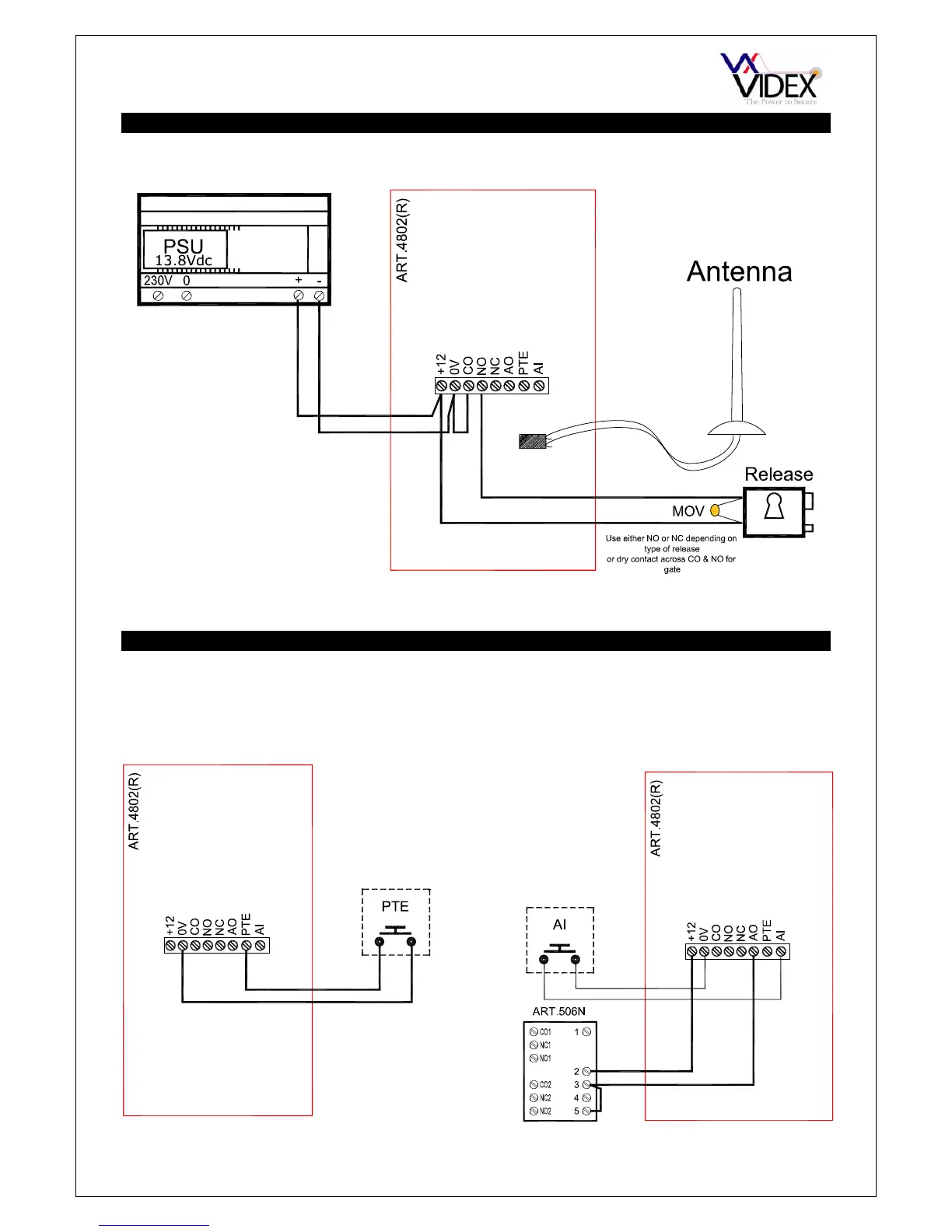
PAGE 8 of 32 DIGITAL GSM INTERCOM TECHNICAL MANUAL VER2.1.1
WIRING DIAGRAMS
PUSH TO EXIT BUTTON AND AUXILIARY INPUTS/OUTPUTS
Connections for push to exit button
Connections for auxiliary input (Switched 0V)
and auxiliary output (Connected to 506N relay)
Auxiliary output is also triggered by pressing 6
on the handset during a call.