66250675-EN - V1.0 - 05/09/17
22
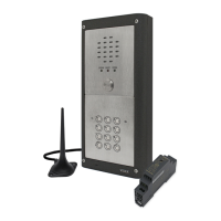
4000 Series Vandal Resistant GSM Audio Intercom with Proximity Facility
4000 Series Vandal Resistant GSM - Technical Manual
Additional Modules
CONNECTING THE VR4KPPM TO THE GSM INTERCOM
Follow the connections as shown in Fig.17 when connecting the VR4KPPM Wiegand proximity module to the GSM intercom when
using the ‘plug-in’ proximity connection harness. The table below shows the harness signal colours.
Connection Signal Harness Wire Colour
1 +LR red wire linked across to terminals 3 and 8 (+positive).
2LR orange wire (red LED).
3+LG red wire linked across to terminals 1 and 8 (+positive).
4LG green wire (green LED).
5 D1/DATA yellow wire (data)
6 D0/CLOCK/DATA white wire (data).
7 black wire (0V).
8+ red wire linked across to terminals 3 and 1 (+positive).
+LR
-LR
+LG
-LG
D1/DATA
D0/CLOCK/DATA
Art. VR4KPPM (XPROX)
CN3
CN1
USB
CN6
CN5
Art.150
GSM Unit for VR Panels
Antenna
Wiegand
Button
Harness
UIM-138 USB
VR4KGSM-0
VR4KGSM-1
VR4KGSM-2
VR4KGSM-3
red
black
white
orange
green
yellow

 Loading...