13
5712 717 v1.0
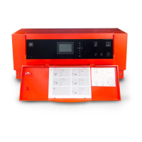
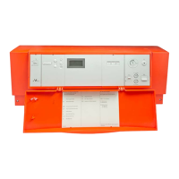
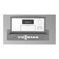
Vitotronic 100, KW10B Installation, Start-up and Service
Electrical Connections
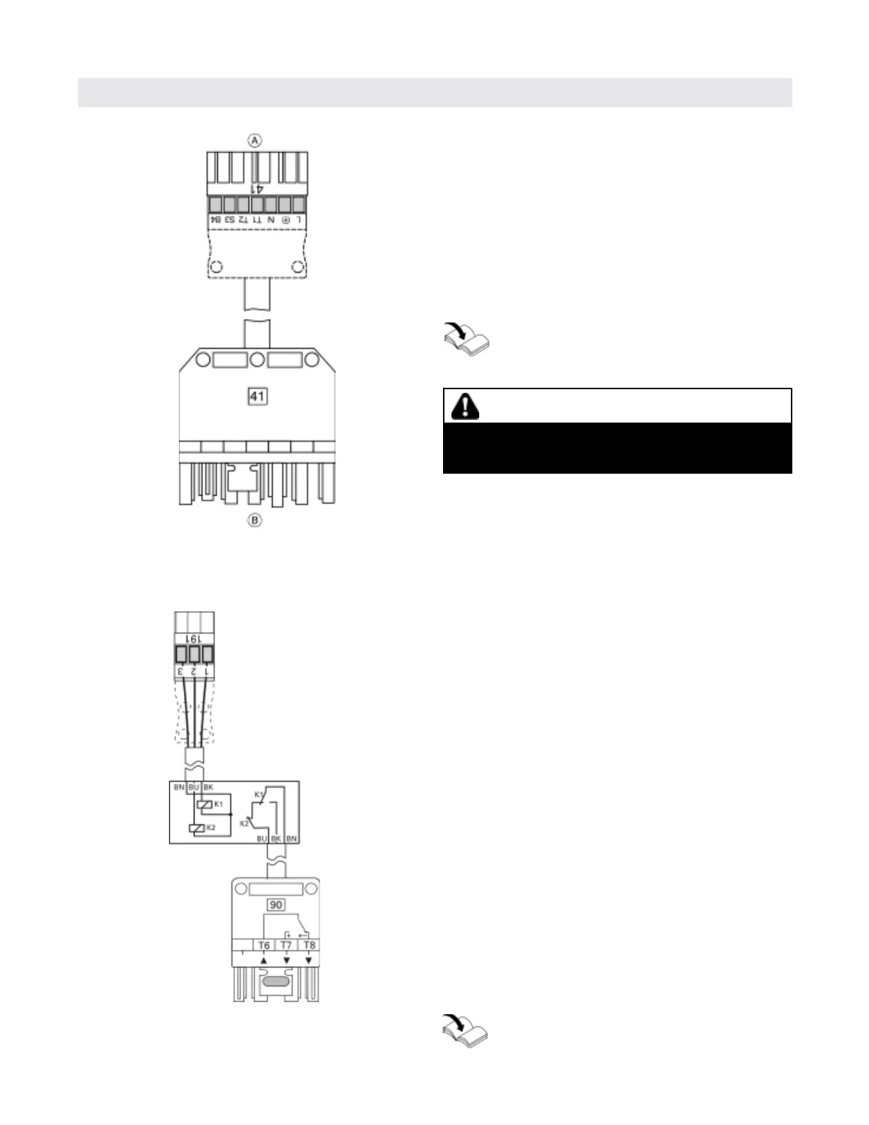
Burner Connection
WARNING
Do not connect the 41-plug from the boiler control
directly to the burner if installing a wall vent system.
See technical instructions of the wall vent system.
The Vitotronic 100 is prewired with the Viessmann
quick-connect plug-in system.
1.
Connect the RAST-5 plug to the main circuit board
of the control
2. Connect 7-pole plug to the counter plug of the burner
or
if installing a wall vent system (accessory), connect
7-pole plug to counter plug of wall vent system.
Refer to technical instructions of the burner
and/or wall vent system.
Terminal codes
T6, T7, Control circuit “two stage burner” or “modulation
T8 controller” (via two-point controller with two
stage operation; via three-point controller with
modulating direction)
q Signal direction:
Control unit g burner
p Signal direction:
Burner g control unit
The connection is made via the extension for 2-stage/
modulating burner.
See Installation Instruction for boiler and
extensiion for 2-stage/modulating burner.
A to control (RAST-5 plug)
B to burner or wall vent system (fA plug)
C to control unit
D enclosure with potential free burner control output
E to burner
C
D
E
 Loading...