28
5712 717 v1.0
Vitotronic 100, KW10B Installation, Start-up and Service
Diagnostics (for qualified service personnel only) (continued)
Test points
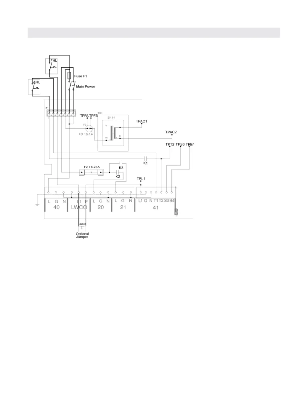
120V power flow
The controls connected power cord is fastened to terminal
40 L/G/N of the control. This provides 120VAC voltage to
the PCB on the X2 terminal strip. The 120VAC is routed
to the X1 quick disconnect plug where the main power
switch is terminated.
The power switch, switches two legs of the 120VAC
voltage power supply. One leg of the 120VAC is fed
through the power switch to the F2 fuse inside of the
control which fuses the two pump outputs 20 and 21.
The second leg of the power switch routes 120VAC to
the main F1 fuse.
From the F1 fuse, 120VAC is supplied to the fixed high
limit (FHL) as well as the fuse for the transformer located
inside of the control F3.
The FHL, if closed, allows the 120VAC signal to be routed
through the PCB to the L1 connection on X2 for the
LWCO. The LWCO, if closed will allow the 120VAC to
be present at P of the X2 terminal strip.
The 120VAC signal will be present at L1 of the 41
burner plug, which can be verified at TPL1. The burner
connection allows the signal to be re-routed to the T1
of the 41 burner plug, The 120VAC signal is then routed
through x1.2 to the adjustable high limit (AHL).
The AHL connection routes the 120VAC signal back onto
X1.1 terminal on the PCB.
When there is a call for heat signal present in the control,
the 120VAC signal shall be present on the contacts of the
K1 relay which can be measured at TP-T2 and confirmed
with the burner firing. As soon as the call for heat is no
longer present, the burner call for heat will stop.
N
TPFA - 120V after F1 before F3
TPFB - 120V after F3 before primary of transformer
TPAC1 / TPAC2 - 24VAC output of transformer
TPL1 - 120V after F1, FHL and LWCO
TPT2 - 120V after AHL and K1
TPS3 - Status from burner
TPB4 - Hour counter from burner
All test points are with respect to neutral except for
24VAC output of transformer.
Troubleshooting
 Loading...