30
5712 717 v1.0
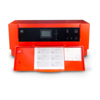
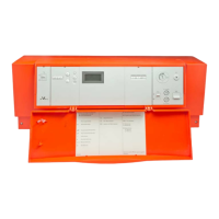
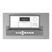
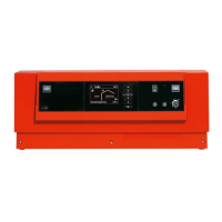
Vitotronic 100, KW10B Installation, Start-up and Service
CAUTION
Connected low temperature (floor heating) systems,
whether connected with or without mixing valves,
must be deactivated during this procedure. Attached
DHW tanks must be isolated and proper water
expansion to the expansion tank must be guaranteed
before performing this test.
CAUTION
Boiler and burner must be supervised during entire
procedure. Allow boiler water temperature to cool down
to 140° F (60° C) before activating any attached heat
distribution system.
CAUTION
FHL test connection is a 120 VAC circuit!
Testing the FHL
A test can be performed to ensure proper operation of the
FHL. Make sure all of the necessary safety precautions
are taken before the test is started.
Power down the control by using the power switch
located on the front of the control. Disconnect the 120V
power supply to the control.
Locate the AHL from within the control and remove the
two wires connected to it, leaving the third green ground
wire connected to the limit. Locate the AHL jumper in the
accessory bag. Insert the one end of the jumper into one
of the connectors removed from the AHL in the previous
step. The other end of the jumper will be inserted into the
other connector removed from the AHL.
Once the jumper is correctly installed, reconnect the 120V
power supply to the control, turn the control ON with
the power switch which was previously turned OFF. A
thermostat terminal call for heat is required to generate a
continuous heat demand to allow the boiler to fire above
the FHL setting.
Once the FHL temperature is exceeded, the burner will
shut down. The boiler will need to cool down sufficiently
to allow the FHL to reset. Press the center of the FHL
with a pen or small screwdriver. A click may be heard or
felt once it has completely reset.
When the test is completed, disconnect the 120V
power supply to the control, turn the power switch off.
Disconnect the wires from the AHL jumper connector and
reinstall the wires to the back of the AHL.
Once the wires have been returned to their original
location on the AHL, reconnect the 120V power supply
to the control, turn the control ON with the power switch.
Remove the thermostat terminal call for heat to verify
the burner shuts down.
Return AHL jumper back to the accessory bag.
Troubleshooting
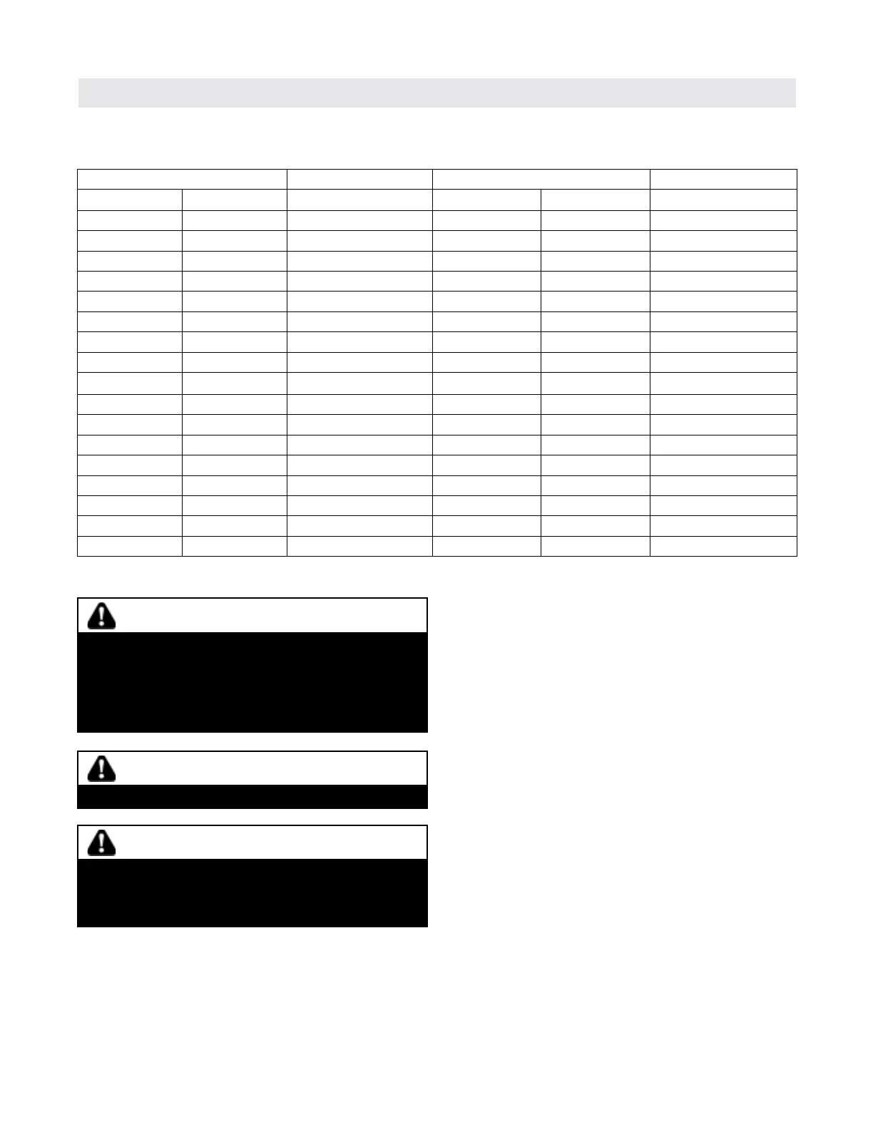
Temperature Resistance Temperature Resistance
°F °C
Ω
°F °C
Ω
-40 -40 336,050 113 45 4,367
-31 -35 242,397 122 50 3,601
-22 -30 176,785 131 55 2,985
-13 -25 130,295 140 60 2,487
-4 -20 96,999 149 65 2,082
5 -15 72,906 158 70 1,752
14 -10 55,301 167 75 1,480
23 -5 42,315 176 80 1,256
32 0 32,650 185 85 1,070
41 5 25,394 194 90 916
50 10 19,903 203 95 787
59 15 15,714 212 100 678
68 20 12,493 221 105 587
77 25 10,000 230 110 510
86 30 8,056 239 115 444
95 35 6,530 248 120 388
104 40 5,325 257 125 341
Boiler and DHW temperature sensor resistance chart
To verify the operation of the boiler and DHW temperature sensor use the chart below.
Diagnostics (for qualified service personnel only) (continued)
 Loading...