27
5712 717 v1.0
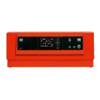
Vitotronic 100, KW10B Installation, Start-up and Service
Failure, cause, correction
o Are all controls operating properly (i.e. thermostats,
low water cut-off, etc.)?
o Are all wire connections tight and secure?
*
1
Red LED does not flash when Honeywell S8600 ignition control module is used with boiler.
Diagnostics (for qualified service personnel only)
Troubleshooting
Symptom/Condition Cause Correction
Boiler control is not active
(GREEN power LED is not illuminated)
Power switch “8“ is in “0“ position Ensure power switch “8“ is in “I“
position.
Main power to boiler control and
heating system has not been
activated
Activate main power; ensure
120 VAC is supplied to control
(receptacle).
Fuse on Vitotronic boiler control has
deactivated heating system
Replace fuse in control with same
type and rating
(F1: T 6.3 A / 250 V, slow blow).
Burner does not activate, or activates
intermittently
(RED fault LED flashes)
Burner is not electrically connected
Ensure 7-pole f
A plug-in connection
to burner and/or power venter is/are
made.
Fixed high limit (FHL) tripped Reset FHL by pushing in the pin,
labelled with a “E“ (using a
ballpoint pen).
If a “click” can be heard, the limit
was tripped.
No fuel *
1
with oil: Ensure sufficient supply of oil
with gas: Open main gas supply valve
or
contact your local gas utility
Pumps on continuously F1 fuse blown Replace fuse
Burner does not activate Control calls for heat but burner does
not respond *
1
Attempt to reset burner using reset
button on the burner
(underneath burner hood).
Service burner if necessary.
Refer to troubleshooting section in
burner manual.
Control calls for heat but burner does
not respond
Power venter has to have separate
120 VAC power supply to motor (see
power venter instructions).
Refer to troubleshooting section in
power venter manual. Air proving
switch, blower wheel or timer/relay
inside power vent may be defective.
Other accessory defect
Ensure proper operation of all
accessories; replace if necessary.
Refer to technical literature supplied
with accessories.
F1 fuse blown Replace fuse
Continuous burner call F3 Fuse blown Replace fuse
Override switch on Turn off override
 Loading...