6
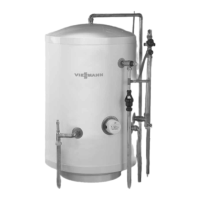
Connections
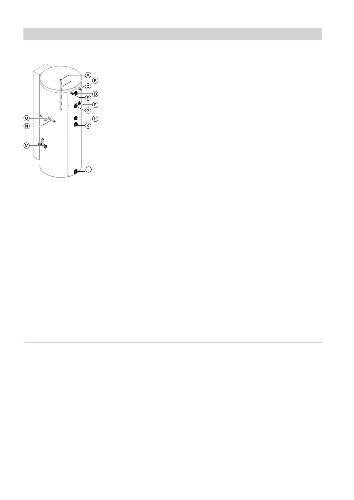
Fig. 1
A
Thermometer sensor connection
B
Magnesium anode with earth cable
C
Heating water return, solar (lower indirect coil, col-
lector connection)
D
DHW to pipework
E
Heating water flow, solar (lower indirect coil, col-
lector connection)
F
Sensor well for cylinder temperature sensor of the
boiler control unit
G
Heating water flow, boiler (upper indirect coil)
H
DHW circulation
K
Heating water return, boiler (upper indirect coil)
L
Cold water/drain outlet
M
Heating water return, solar (lower indirect coil, con-
nection to heat exchanger)/sensor well for cylinder
temperature sensor, solar
N
Sensor well for lower thermometer
O
Heating water flow, solar (lower indirect coil, con-
nection to heat exchanger)
Siting information
!
Please note
The thermal insulation must not be able to come
into contact with naked flames.
Exercise caution when welding and soldering.
!
Please note
To prevent material losses, site the DHW cylin-
der in a room free from the risk of frost and
draughts.
When not in use, the DHW cylinder must be
drained if there is a risk of frost.
Use the adjustable feet to level the DHW cylinder.
Note
Never extend the adjustable feet beyond a total length
of 35 mm.
Preparing for installation
5838620
 Loading...