29
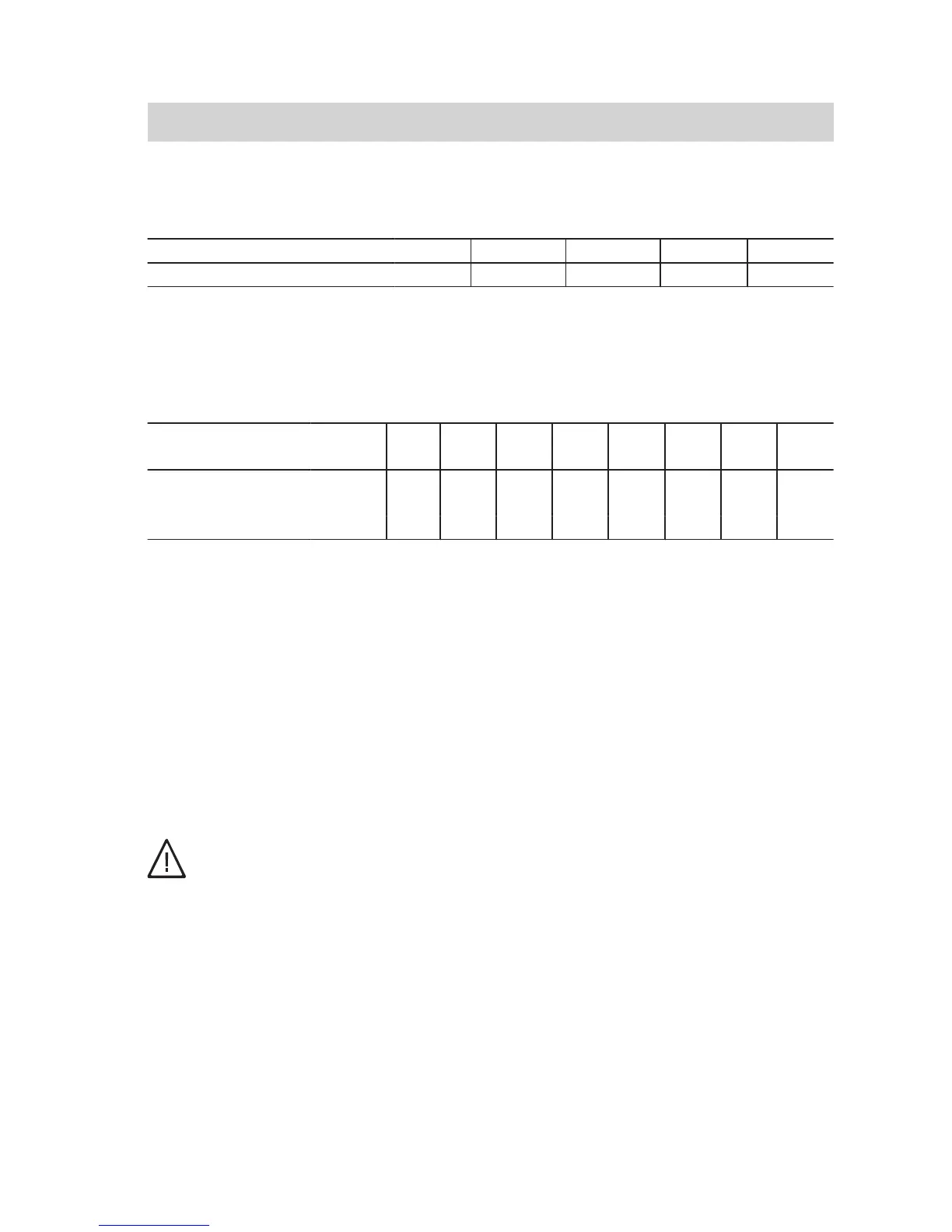
Maximum flue length
Vitodens 100-W, type B1HA and B1KA, Vitodens 111-W
Rated heating output kW 19 26.0 30.0 35.0
System size 80 m 20 20 25 25
Note
For system size 80, an adaptor is
required.
Vitodens 200-W, 222-F and 242-F
Rated heating
output
kW 13 19 26 35 45 60 80 100
System size 60 m 18 18 — — — — — —
System size 80 m 25 25 25 25 20 15 — —
System size 100 m — — — — 22 17 20 20
The following components are taken
into consideration for the maximum flue
lengths:
■ Connection pipe 0.5 m long
■ 1 flue bend 87° and 1 support bend
87°
or
■ 2 flue bends 45° and 1 support bend
87°
Subtract other bends, tees and straight
lengths from the maximum length using
the following values:
■ Connection pipe 0.5 m long: 0.5 m
■ Connection pipe 1 m long: 1 m
■ Flue bend 45°: 0.3 m
■ Flue bend 87°: 0.5 m
■ Inspection tee: 0.3 m
Installation
Danger
To ensure correct function, route
the flexible flue at a maximum
angle of 45° from the vertical.
Never pull the flexible flue pipe
over sharp edges during instal-
lation.
Note:
■ Always draw the flue pipe in from the
top downwards.
■ Observe flow direction (arrow on
components).
■ Subject to shaft size, install spacers
at intervals of max. 2 m.
■ Insert a spacer before and after any
change in direction and any inspec-
tion piece.
■ The flue must not come into contact
with the shaft wall.
Routing through a shaft
(cont.)
5780 223 GB