45/46
4Vitolig 200
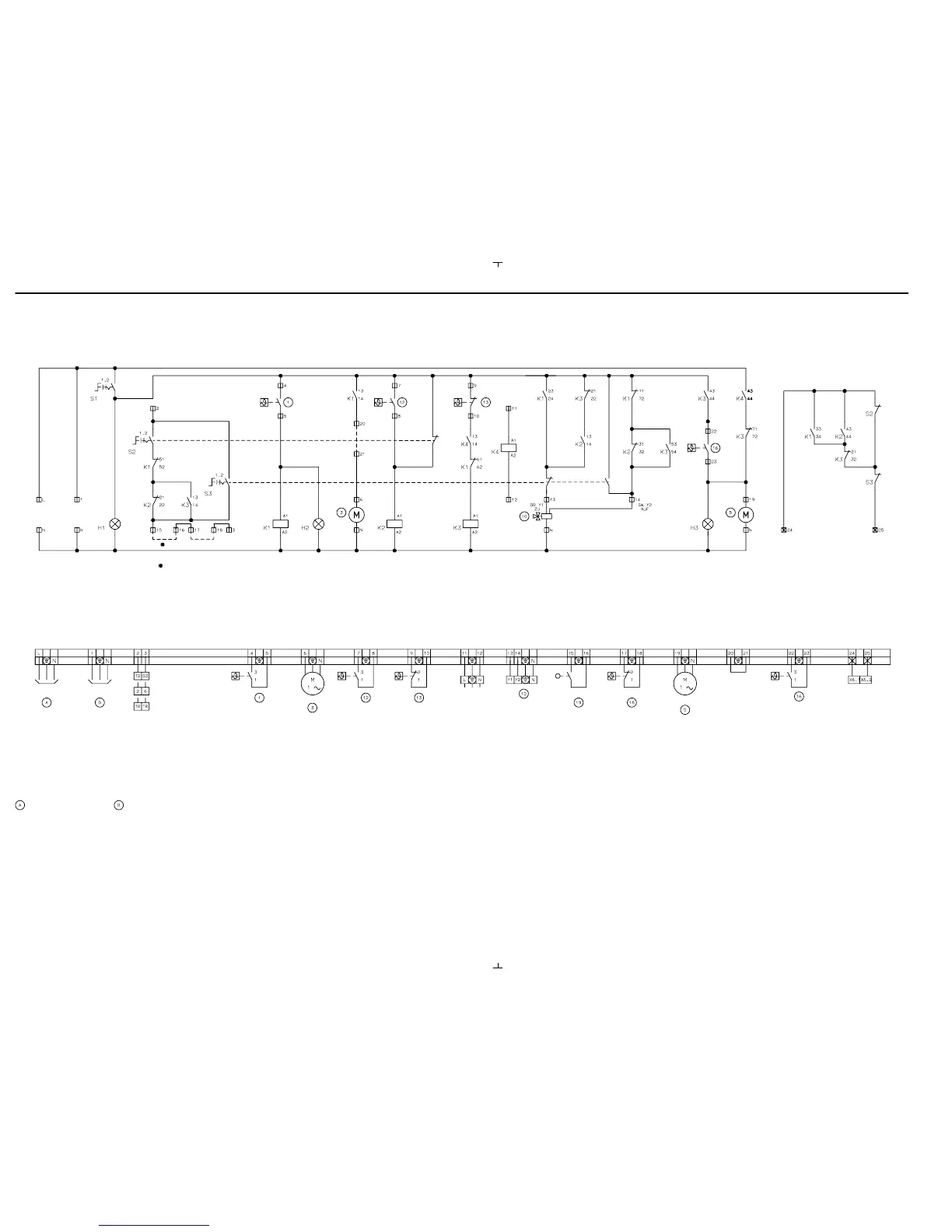
Wiring diagram of the connection box qU for Vitolig 100/200
5822 241 GB
Vitolig 100:
Minimum
temperature regulator
Vitolig 200:
Contact thermostat
Control
thermostat in the
heating water
buffer storage
unit
Control
thermostat in the
heating water
buffer storage
unit
Plug 21 of
Vitotronic
Three−way
changeover valve
(connection unit)
Circulation pump
for DHW cylinder
heating
Extend the terminals
to connect an
additional flue gas
temperature monitor
for Vitolig 100
Control thermostat in
the oil− or gas−fired
boiler or the
wall−mounted
gas−fired boiler
Coding on Vitotronic 200 or 300:
Connection of the boiler
circuit pump 3
Vitolig 100:
At terminals 6/PE/N in
the connection box
Vitolig 200:
At terminals LV 230 V AC
X2/N/PE (boiler circuit
pump)
Bridged in the
"as delivered"
condition
Terminals on plug 150
Dekamatik
Terminals at terminal strip
X6 Viessmann Trimatik
Terminals on plug 150
Vitotronic
Door interlock
switch
Flue gas
temperature
regulator
Remove jumpers when
connecting the boilers to
a common chimney
Terminals at plug X6
Vitopend 200 or Vitodens
61 : 10 on 61 : 1 change: Circulation pump for DHW cylinder heating
activated irrespective of boiler temperature
62 : 10 on 62 : 0 change: Circulation pump for DHW cylinder heating
immediately deactivated, without run−on
Mains electrical connection
230 V/50 Hz install mains
isolator in line with
regulations
Main fuse max. 16 A
Mains electrical connection 230 V/50
Hz for boiler control unit Vitotronic 200
KW2 or 300 KW3
S1Vitolig Off − On
S2Oil−/gas−fired boiler Off − Automatic
S3Emissions test switch
H1 Operation
H2 Vitolig operation
H3 Circulation pump operation
for DHW cylinder heating
Control thermostat illustration shows the cold state
 Loading...