4 Vitolig 200
51
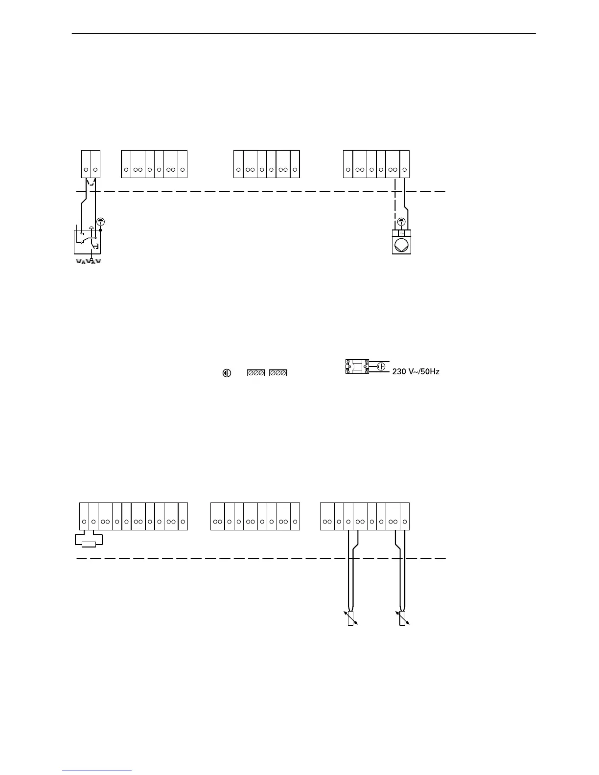
Wiring diagram for application example 3
Boiler circuit pump and low water indicator connections
Temperature sensor for heating water buffer storage unit connection
5822241 GB
XN/N
XN/LI
Mains electrical connection
XW Buffer loading controllerHeating circuit 2Heating circuit 1
Boiler circuit pump 2
Low
water
indicator
eT
1
N
2
X44
X65
N
6
X98
3
7
X2
1
2
1
N
2
X44
X65
N
6
X98
3
7
X2
1
N
2
X44
X65
N
6
X98
3
7
L
N
X2
R2
120 Ohm
Heating circuit 1
1
2
Y34
Y45
Gnd
6
Y58
3
7
Y2
Y79
Gnd
10
11
L+12
L−13
Gnd
Heating circuit 2
1
2
Y34
Y45
Gnd
6
Y58
3
7
Y2
Y79
Gnd
10
11
Gnd
Buffer loading controller
Buffer
temperature
sensor
top qQ
1
2
Y34
Y45
Gnd
6
Y58
3
7
Y2
Y79
Gnd
10
11
Gnd
Buffer
temperature
sensor
bottom qW