5 Vitolig 100
C qR
PE
M
1~
12 14
11
N
L
A B
2
64
Explanations regarding specific Vitolig 100 connections and functions
The application examples 2 and 3 with
hydraulic designs for Vitolig 200 also
apply to Vitolig 100, except for the
variations described in the following.
Regarding application example 2 (pages 39 to 46)
The minimum temperature regulator
integrated into Vitolig 100 is connected to
terminals $ and % in the connection
box qU, and replaces the separate
minimum temperature regulator 1
required for Vitolig 200.
The flue gas temperature monitor qI is
connected to terminals sÖ and sA
(remove existing wire jumper).
Regarding application example 3 (pages 47 to 54)
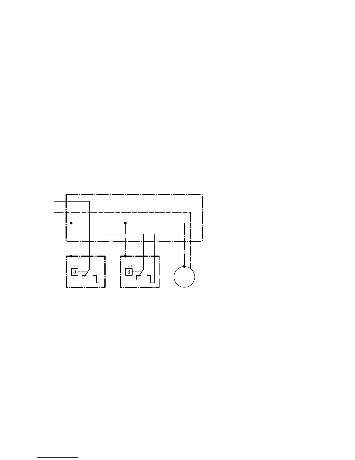
Boiler circuit pump 2 connection
The boiler circuit pump 2 is switched
on, if the temperature set at the minimum
temperature regulator and at the flue gas
temperature monitor qR is exceeded.
A Mains electrical connection
230 V, 50 Hz
B Connection box (on site)
C Minimum temperature regulator 1 in
Vitolig100
Connection of Vitolig 100 and one oil− or gas−fired boiler to a common chimney
See page 52.
5822241 GB
 Loading...