Control Connections
38
Electrical Connections
(continued)
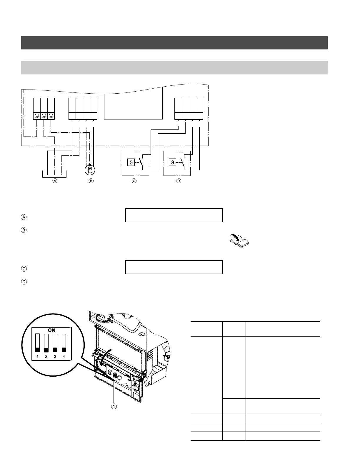
Electrical connections to the power pump module
X2 X4 1 2 3 4X3 L N N L
120V
PUMP
RT
Note:
Boilers are factory shipped with
a wiring diagram (11”x17” page
inside a pouch) attached to the
inside of the front cover. The
wiring diagram shipped with the
boiler supercedes the wiring in-
formation in this manual.
Provide main power disconnect/service switch as per local code
requirements. Also refer to wiring diagram on page 71.
DHW
Legend
Main power supply
(120V, 60Hz, 1 PH).
Heating circuit pump (or boiler
pump with low-loss header
application). See DIP switch
selection setting S1 below. (Pump
runs for 10 seconds every 24
hours).
DHW tank temperature controller /
external heat demand
Room temperature thermostat
(Anticipator setting 0.2A)
DIP switch settings - S1
Remove short factory test leads from
terminal L, N and Ground before
connecting main power supply to
boiler.
Ensure that pressure activated by-pass
is installed with system layout 1 on
page 28.
Note:
If the boiler is operated using a 10VDC
modulating signal...
See separate OpenTherm (OT)
Module Installation
Instructions.
DIP switch settings - S1
Dip switch
number
Setting Explanation
1 OFF Pump B is ON during call
for heat. After call for heat
(RT-Terminal) is satisfied
pump B post-purges for
12 mins.
After DHW/external heat
demand (ST-Terminal) is
satisfied, pump B post-
purges for 1.5 minutes (see
important note above).
ON Pump B operates continu-
ously
2 OFF Do not adjust
3 OFF Do not adjust
4 OFF Do not adjust
5581 775 1.3
S1
Factory default settings
for S1 DIP switch
1 Dip switch S1
IMPORTANT
IMPORTANT