Troubleshooting
64
Diagnosis
(continued)
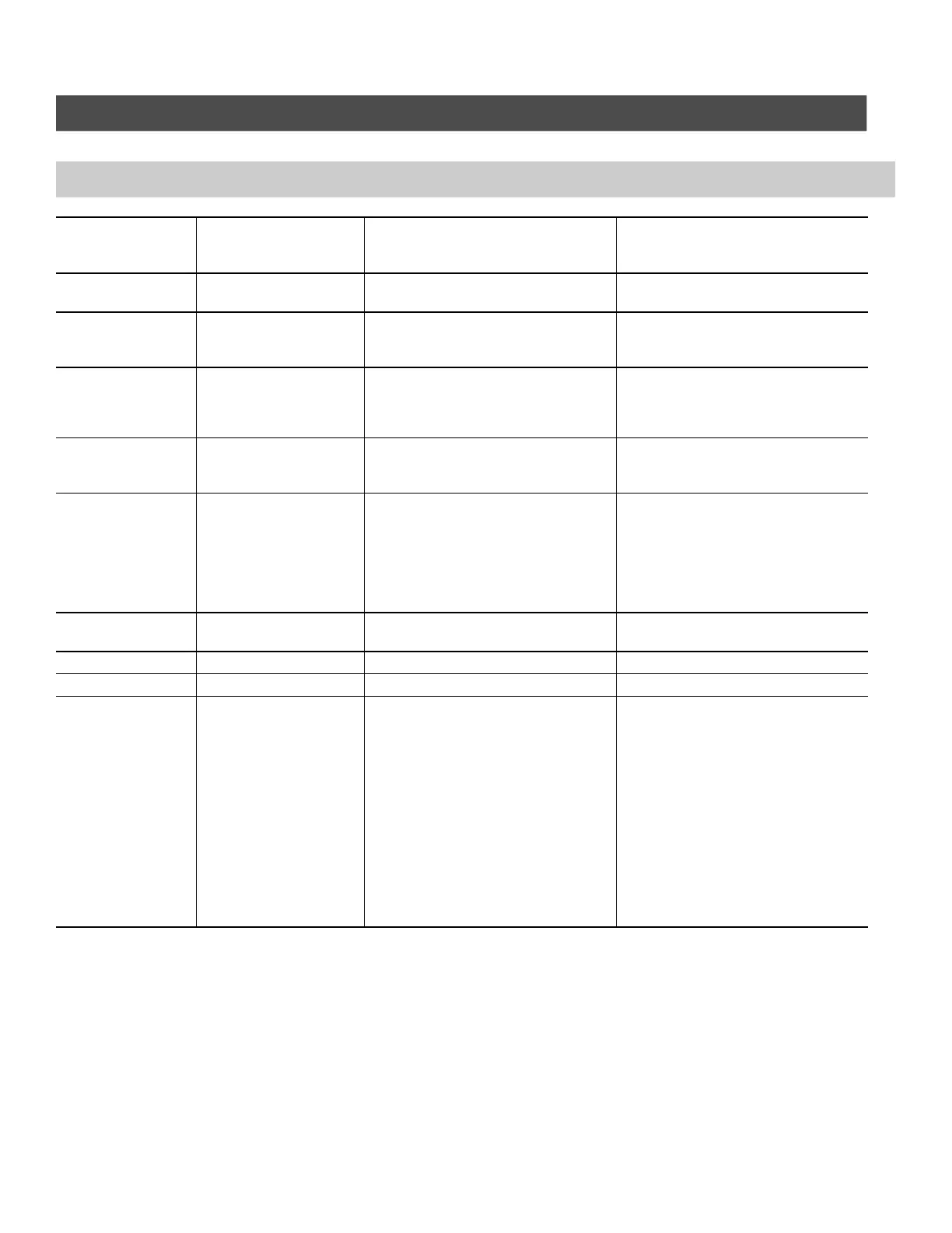
Diagnostics table: Faults with fault display on control unit (continued)
Fault mes-
sage in dis-
play window
System behavior Cause Corrective measures
f7
Burner blocked Faulty water pressure sensor Check the water pressure sensor and
the interconnecting cable.
f8
Burner in fault mode Combination gas valve closes too
late
Check the gas combination valve.
Check both air and gas paths.
Press “Reset”.
f9
Burner in fault mode Blower speed too low at burner start Check the blower, check the blower
cables and supply, check the blower
control.
Press “Reset”.
fa
Burner in fault mode Blower not at stand-still (blower
must be in stand-still when in stand-
by mode)
Check the blower, check the blower
cables, check the blower control.
Press “Reset”.
fd
Burner blocked Burner control unit fault Check the ignition electrodes and
leads. Check whether a strong inter-
ference (EMC) field exists near the
equipment.
Press “reset”.
If the fault is not removed, replace
the control unit.
fe
Burner blocked Faulty main PCB If the equipment will not restart after
resetting, replace control unit
18
Burner in fault mode DIP switch S2 is set to “ON” Set DIP switch S2 back to “OFF”
58
Burner in fault mode DIP switch S4 is set to “ON” Set DIP switch S4 back to “OFF”
a9
Non-permanent lock-out
(burner in fault mode)
Communication error OpenTherm
Module
Turn boiler OFF, then ON
Check communication cable on Ter-
minals X3.3, X3.4 on boiler controls.
Check connection on OT-Module sub
base Terminals 12, 13.
Check 24VAC output of PPM of the
boiler Terminals X4.3, X4.4 (RT Ter-
minals).
Check for 0-10VDC input signal (a
min. of 3.0 volts is required to start
up the boiler).
5581 775 1.35581 775 1.3