Troubleshooting
41
Correction (continued)
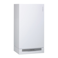
Check DHW tank temperature sensor or low-loss header temperature sensor
A DHW tank temperature sensor
B Low-loss header temperature sensor
1. Disconnect connector ”X7” from the
control unit.
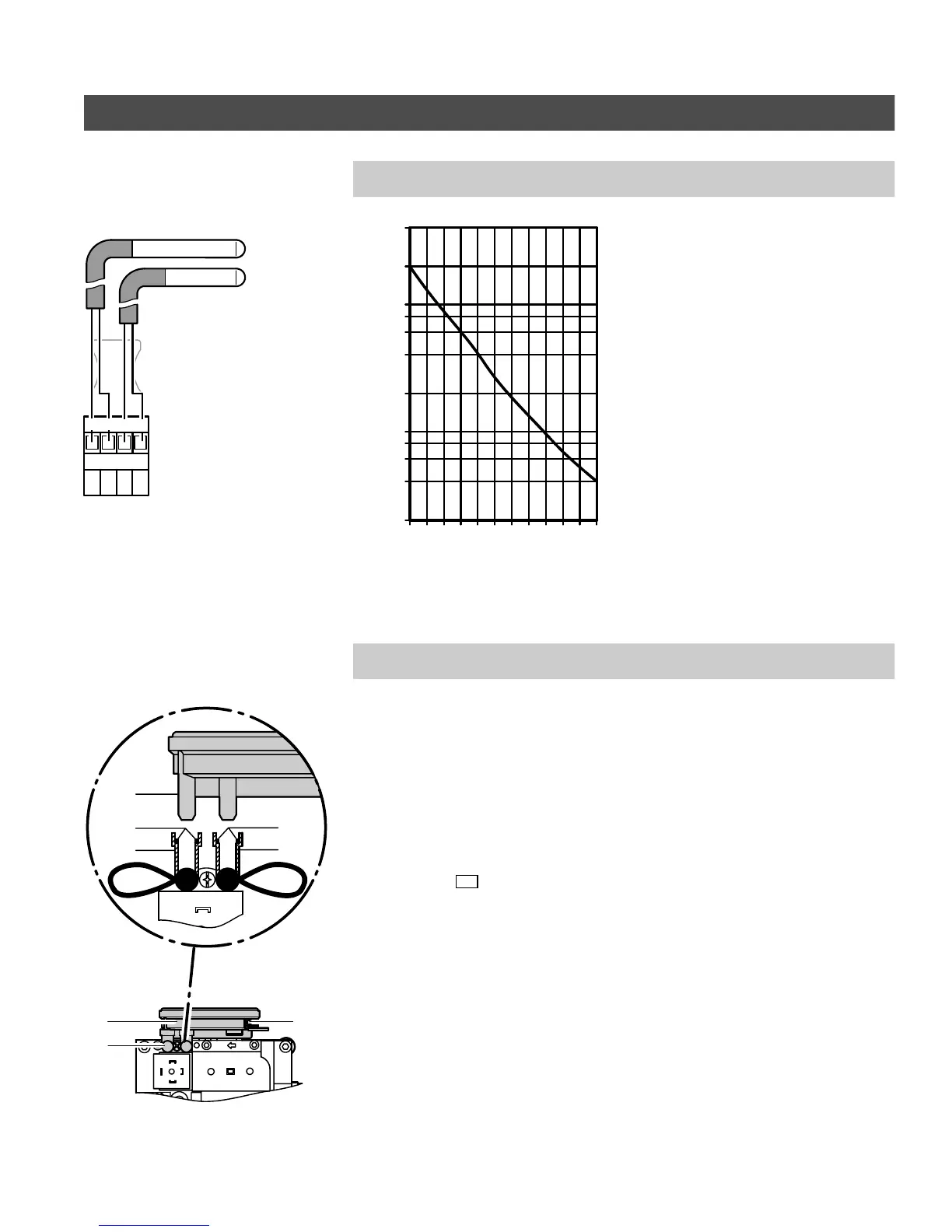
2. Measure resistance of the tank
temperature sensor and compare
with the curve.
3. If the value measured differs
significantly, replace the sensor.
4. Repeat above steps 1 - 3 for
checking the low-loss header
temperature sensor.
Check and replace differential air pressure sensor
In case of fault messages regarding the differential air pressure sensor, check that
H the sensor was installed correctly.
H the electrical connections were made correctly.
H the O-rings in the adaptor are c orrectly positioned.
H the test nipples have been sealed with plugs.
If the error message persists, replace sensor.
To check O-rings:
1. Disconnect electrical plug-in
connection
164
A.
2. Remove sensor B by pulling off in
an upward direction.
3. Check that the two O-rings C are
correctly located in the mountings
D of the adaptor.
4. Insert connection nipples of the
sensor in the adaptor of the gas
combination valve and snap into
place.
5. Reconnect the electrical plug-in
connection on the sensor.
Transducer power supply
X14.3 Red................
X14.4 Yellow................
X14.5 Black................
Between red and black:
24VDC.......................
Between black and yellow:
at standby 0.2 to 0.3VDC........
at ignition 0.7 to 1.0VDC.........
at low fire 0.5 to 0.6 VDC........
at high fire 3.5VDC........
5285 961 v1.3
X7
3 421
A
B
10
1
0.2
0.4
0.6
0.8
2
4
6
8
20
40
Resistance in k
Tank temperature in ºF/ºC
10 30 50 70 110
20 40 60
80 100 120
50 86 122 158 194 230
68 104 140 176 212 248
Ω
A
D
D
B
B
C
D
C