28
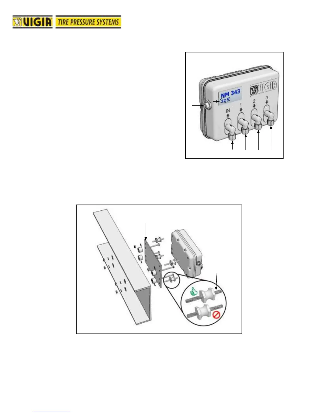
Location of Parts and components
1- Electrical connector (can bus) to the display module
and to the electrical power socket.
2- Voltage indicator (12 or 24 V.).
3- Air Intake from air tank.
4- Pressure 1 to tires.
5- Pressure 2 to tires.
6- Pressure 3 to tires.
Installation Procedure
Secure control module using all support, separators,
rubber pads, bolts and nuts provided. Install to chassis
frame or other vehicle part.
Perforate the plate according to the holes
available in the chassis or as needed
Shortest side
towards the
module.