13
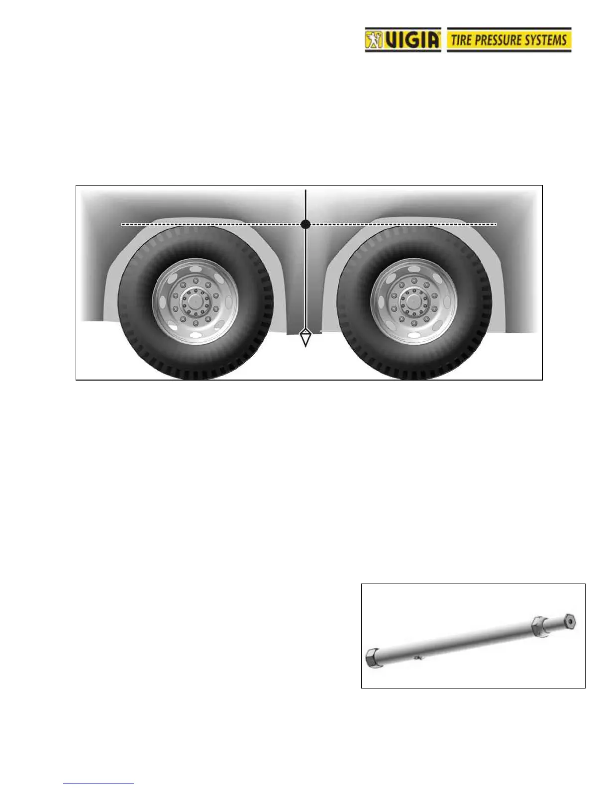
B2. Double axles (Fig. 40)
Note: This procedure applies only when the air pressure in tires of both axles will be the
same. If that is not the case, refer to the procedure for single axles.
1- Using a plumb, determine the centre line between the axles.
2- On the centre line, define a point at the approximate height of the tires, with
respect to floor level.
Before drilling, make sure that there are no
obstructions inside the fender or body. If there
are any obstructions, mark a new position as
close as possible to the point originally marked.
3- Drill first with 5 mm bit (13/64") and then with a
10.25 mm (13/32") bit.
4- Install the double outlet body coupling. If
coupling is under unloading doors, install a
protecting visor.
C- NON-STEERING AXLES WITHOUT FENDERS
An adjustable body coupling mounting pipe is provided
for these axles (Fig. 44).
C1. Single axles (Fig. 45)
1- Find a bolt or hole in the chassis approximately
400 mm (15 ¾”) in front of the tire's centre line,
and at a height that will avoid any rubbing to the
mounting pipe, even with the suspension
working at load limit (Fig. 46).