22
2.5 - HOSE
INSTALLATION PROCEDURE
Given the vast variety of vehicles on the market today,
the hose installation will be subjected to the installer's
criteria. Nevertheless, the following recommendations
will facilitate and optimize the installation:
1- Use only the hose provided with the system.
2- Secure the hose approximately every 40 cm
(16"). If the fastening is near brake air pipes or
electrical connections, use the straps provided.
If the fastening is on the chassis or body, use
the special clips and clamps also provided.
3- Drill the required holes with care. Be sure not to
damage pipes, tanks, electrical components,
etc.
4- Do not install hoses near heat sources (mufflers,
heating pipes, etc.) or moving parts (steering,
suspension, cross-arms, etc.).
5- Near body couplings, secure the hose at shorter
lengths, so that if a clip or a clamp gets loose,
the hose does not come into contact with the
tire.
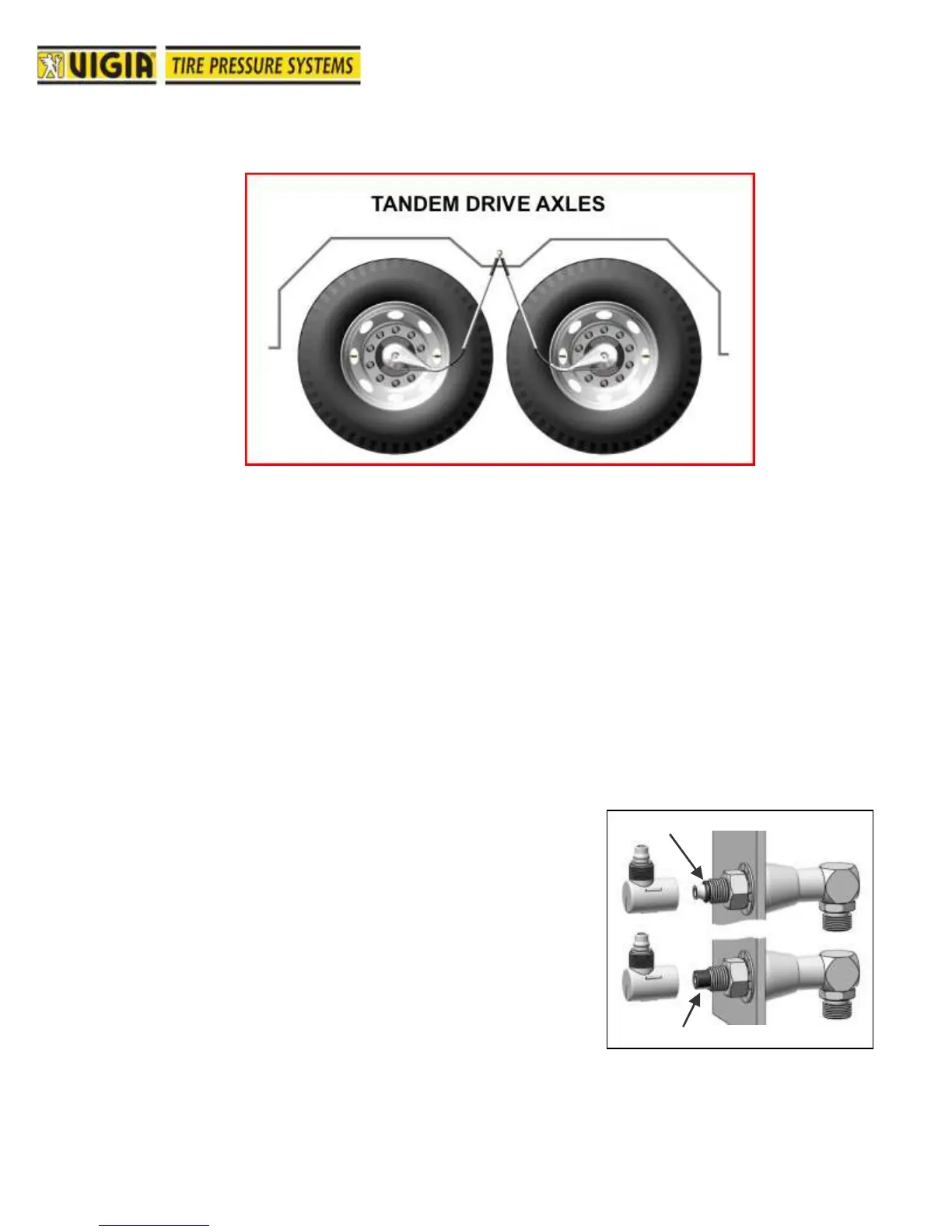
6- If a body coupling is too close to the wheels and
it becomes necessary to bend the hose in a 90-
degree angle, use an elbow connector
(provided). To install it, insert a piece of hose
into the body coupling terminal and cut it flush,
so that it works as a joint to prevent leakage A
“O” ring can be used instead.(Fig. 53).