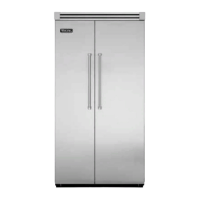
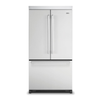
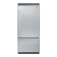
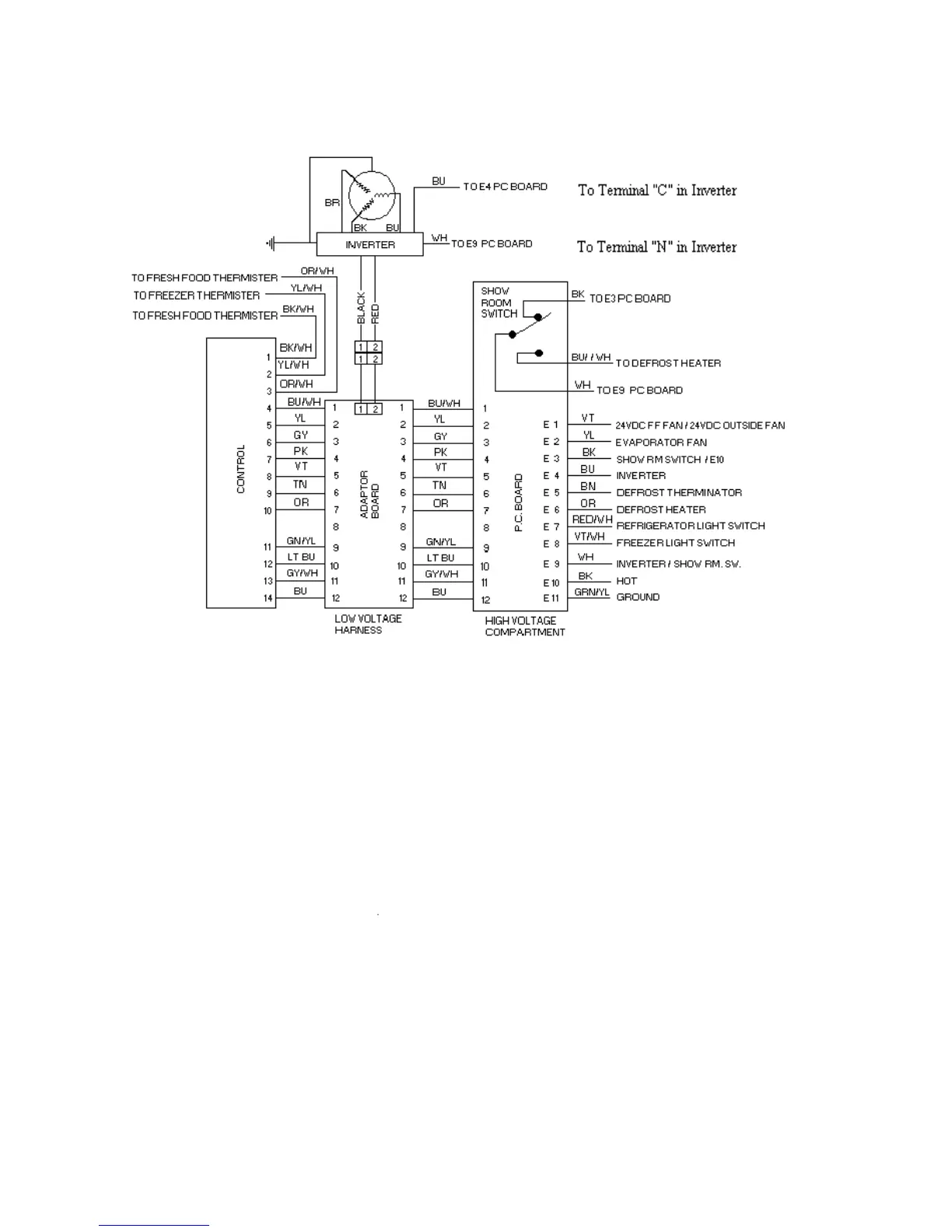
VARIABLE CAPACITY COMPRESSOR (VCC)
CONTROL UNIT
The adapter board sends a frequency signal to the inverter. Typically the adapter board
will send a 3mA current and 5VDC (square wave) signal. The frequency can be checked
with a Fluke meter that reads frequency. There is a self check provision on the adapter
board that occurs during the first 45 seconds after the refrigerator is powered up. If you
remove the frequency wire from the inverter (going to the control housing), you can
probe the pins with the Fluke meter. With the probes from the Fluke meter (making sure
the meter is in the frequency mode) on the pins from the adapter board wiring harness,
power up the refrigerator. The meter should see the two frequencies called out in the
Adapter board drawing. The frequencies will fluctuate every 15 seconds until the time
reaches 45 seconds (15, 30, 45 sec.) The frequencies are listed on the adaptor board
drawing and the compressor drawing. The adapter board sends two separate frequencies
depending on several factors. At startup or after power restoration the adapter board
sends the inverter the high frequency signal until the first defrost. After the first defrost,
it sends the lower frequency signal. The adaptor board will also go into the higher
frequency under two other conditions, if the runtime (called the Runtime High Trigger)
reaches a specific time or if the duty cycle reaches a specific %. The adapter board will
resort back to the lower frequency in both cases when the Duty Cycle drops below a
specific %.
29