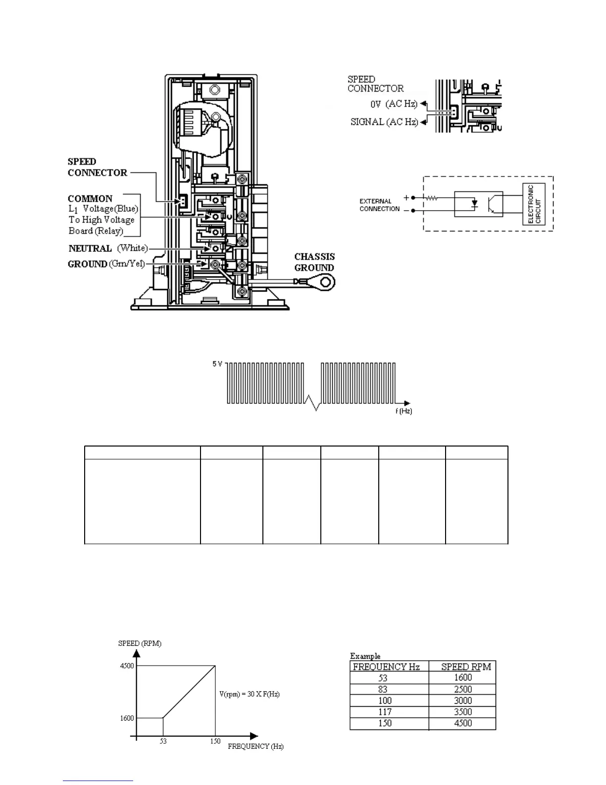
Speed Control Interface
1. Position:
2. Circuit:
3. The microcomputer will wait for
a speed information in order to
start.
4. The speed signal wave form (continuous pulse train) shall be as follows:
5. The maximum and minimum rating for speed input signals are:
INPUT VOLTAGE SYMBOL Min Type Max Unit
HIGH Vhigh 4.5 5.0 5.5 V
LOW Vlow -0.2 0 0.2 V
REVERSE VOLTAGE VR 6 V
ISOLATION VOLTAGE
(AC for 1 min.) Viso 5 V
FORWARD CURRENT IF 3 5 10 mA
REVERSE CURRENT IR 10 µA
The pulse frequency (edge sensitive, duty cycle from 10 to 90% is OK) will determine the motor
speed as shown in the curve below:
6. Minimum speed 1600RPM -- Maximum speed 4500 RPM
7. If the inverter does not receive the speed signal for more than 33 shaft turns, the motor stops.
30