Installation & User Manual System CTB-100V
14
3.8 Volume and signal adjustment.
Ref. drawing CU-10_lo and CU-20_lo for location.
3.8.1 Substations
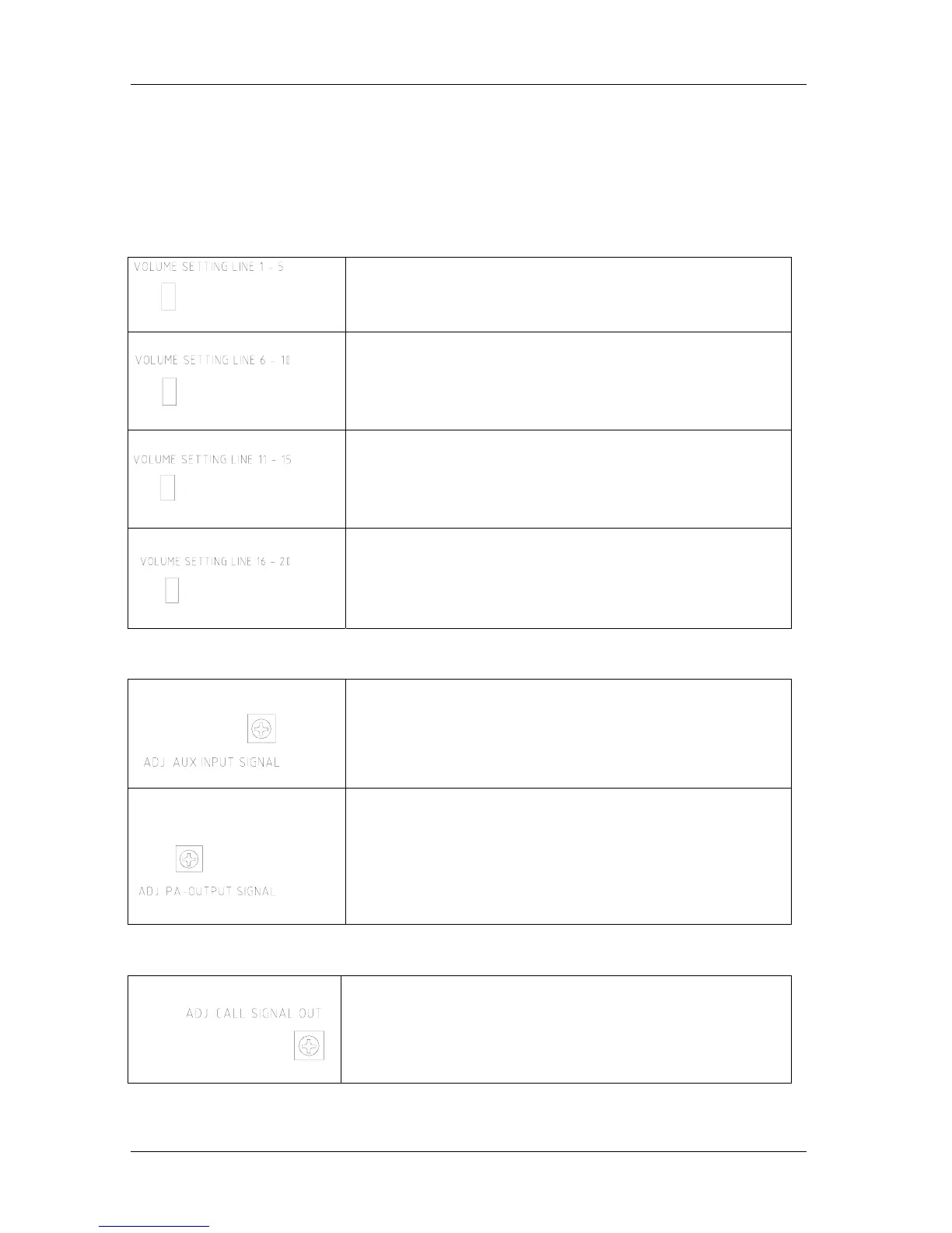
System volume for substations can be adjusted by separate trim potentiometer for each group of 5 lines.
Market “volume setting line 1-5” “6-10” “11-15” “16-20”
System volume is factory adjusted and does not normally require any adjustment.
Volume adjustment for substation line 1 – 5
Trim potentiometer located on mainboard
Volume adjustment for substation line 6 – 10
Trim potentiometer located on mainboard
Volume adjustment for substation line 11 – 15
Trim potentiometer located on additional board CU-20.
Volume adjustment for substation line 16 – 20
Trim potentiometer located on additional board CU-20.
3.8.2 Auxiliary and Public address.
Signal is factory adjusted and does not normally require any adjustment.
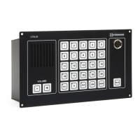
Input signal for auxiliary can be adjusted by separate trim potentiometer
marked “adj. aux.input signal”. Required signal 0dB (0,775V)
Signal for Public address can be adjusted by separate trim potentiometer
marked “adj. pa output signal”.
Signal is factory set to 0dB (0,775V) and does not normally require any
adjustment.
3.8.3 Call signal
Signal is factory adjusted and does not normally require any adjustment.
Level of Call signal out all lines can be adjusted by trim potentiometer
marked “adj. call signal out”