LED Description
OUT
green
● Digital output 6 is set
on: ● | off: ○ | blinks with 2Hz: B
For wires with a cross section of 0.08mm
2
up to 1.5mm
2
.
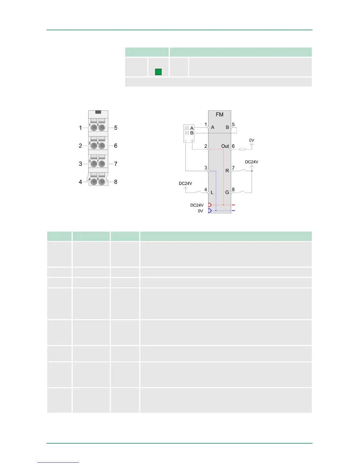
Pos. Function Type Description
1 A I A / pulse
Pulse input for counter signal respectively track A of an
encoder for 1-, 2- or 4-fold evaluation.
2 DC 24V O DC 24V for encoder
3 0V O GND
4 L I Latch
Input to store the current counter value as latch value in the
input area. The storage happens with an edge 0-1 respectively
a level-triggered signal.
5 B I B / direction
direction signal respectively track B of an encoder (invertible
via parameterization)
6 Out O Digital output controlled by means of the comparison func-
tions.
7 R I Reset
Input to reset the counter, if the reset functionality was ena-
bled within the parameterization.
8 G I Hardware gate
Input to control the HW gate. The HW gate is controlled by a
high level.
I: Input, O: Output
Pin assignment
VIPA System SLIO Hardware description
Structure
HB300 | FM | 050-1BA00 | GB | 14-36 33