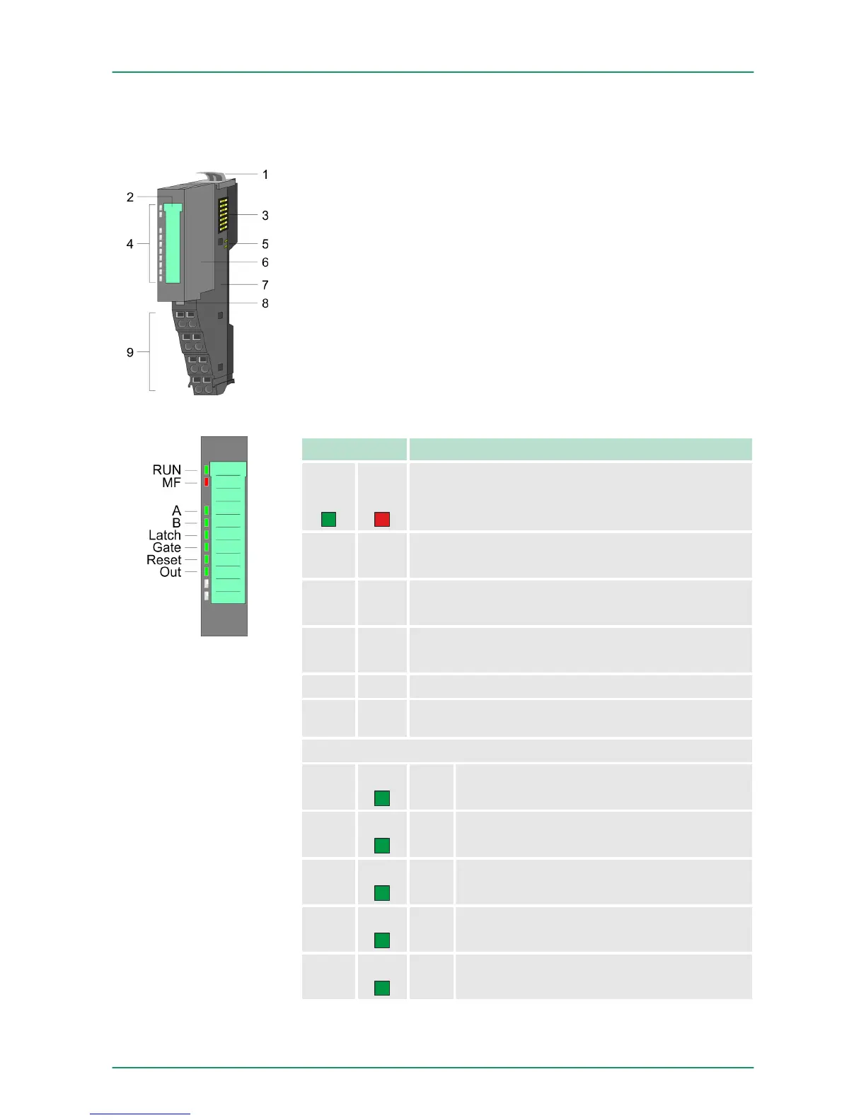
3.2 Structure
1 Locking lever terminal module
2 Labeling strip
3 Backplane bus
4 LED status indication
5 DC 24V power section supply
6 Electronic module
7 Terminal module
8 Locking lever electronic module
9 Terminal
LED Description
RUN
green
MF
red
● ○
Bus communication is OK
Module status is OK
● ●
Bus communication is OK
Module status reports an error
○ ●
Bus communication is not possible
Module status reports an error
○ ○ Error at bus power supply
B B
Error in configuration
Ä
Chapter 2.7 ‘Trouble
shooting - LEDs’ on page 26
A
green
●
Digital input 1
A/pulse is set
B
green
●
Digital input 5
B/direction is set
Latch
green
●
Digital input 4
Latch is set
Gate
green
●
Digital input 8
hardware gate is set
Reset
green
●
Digital input 7
Reset is set
050-1BA00
Status indication
VIPA System SLIOHardware description
Structure
HB300 | FM | 050-1BA00 | GB | 14-36 32