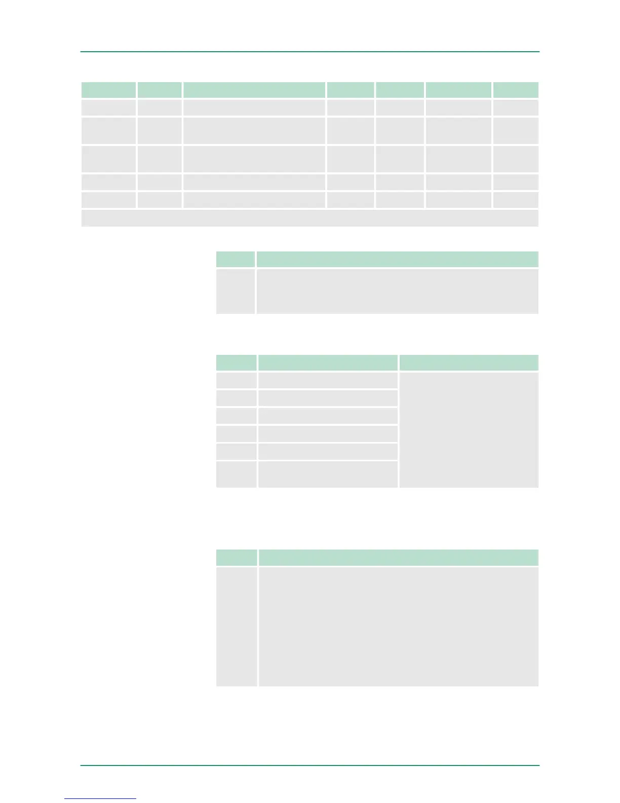
Name Bytes Function Default DS IX SX
MODE3_I 1 Counter mode 3* 00h 80h 310Ah 0Bh
END_I 4 End value 00h 81h 310Bh...
310Eh
0Ch
LOAD_I 4 Load value 00h 81h 310Fh...
3112h
0Dh
HYST_I 1 Hysteresis 00h 81h 3113h 0Eh
PULSE_I 1 Pulse 00h 81h 3114h 0Fh
*) This parameter may only be transferred at STOP state.
Byte Bit 7...0
0 Diagnostic interrupt
n 00h = disable
n 40h = enable
n Here you activate res. de-activate the diagnostic function.
Byte Function Possible values
0 Input frequency track A
n 02h: 100kHz
n 03h: 60kHz
n 04h: 30kHz
n 06h: 10kHz
n 07h: 5kHz
n 08h: 2kHz
n 09h: 1kHz
Other values are not
permissible!
1 Input frequency track B
2 Input frequency Latch
3 Input frequency Gate
4 Input frequency Reset
5 0 (fix)
n Input frequency allows you to preset a filter for I1, I4, I5, I7 and I8.
With the help of filters you may e.g. filter signal peaks at a blurred
input signal.
Byte Bit 7 ... 0
0 Bit 6 ... 0: Interrupt behavior
n Bit 0: Proc. interrupt HW gate open
n Bit 1: Proc. interrupt HW gate closed
n Bit 2: Proc. interrupt overflow
n Bit 3: Proc. interrupt underflow
n Bit 4: Proc. interrupt comparison value
n Bit 5: Proc. interrupt end value
n Bit 6: interrupt latch value
n Bit 7: 1 (fix)
n Setting the appropriate bit activates the associated process inter-
rupt
DIAG_EN Diagnostic
interrupt
CHxx Input frequency
INT_I Interrupt behavior
VIPA System SLIODeployment
Parameter data
HB300 | FM | 050-1BA00 | GB | 14-36 44