Do you have a question about the Viper 350 Plus and is the answer not in the manual?
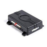
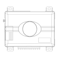
Detailed diagram showing wire connections for the primary harness.
Step-by-step instructions for connecting primary harness wires.
Description of the H1/1 ORANGE wire's function and connection.
Steps to initiate the system feature configuration process.
Guide to selecting, programming, and confirming features.
Lists and describes basic configurable system features.
Lists and describes advanced configurable system features.
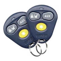
Procedure for teaching transmitters to the system.
Assigning functions to transmitter buttons.
Addresses issues with the starter kill relay and shock sensor.
Solves problems related to door triggers and alarm progression.
Covers passive arming, progressive trigger, and LED issues.
Visual guide for connecting the 12-pin primary harness.
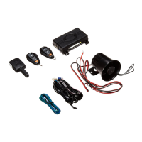
Overview of connections for sensor, lock, and other harnesses.
| Remote Start | Yes |
|---|---|
| Keyless Entry | Yes |
| Shock Sensor | Yes |
| Siren | Yes |
| Remote Range | Up to 1/4 mile |
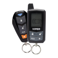
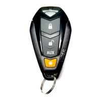
| Number of Remotes | 2 |
| Number of Buttons on Remotes | 5 |
| Alarm System | Yes |
| Starter Kill | Yes |
| LCD Remote | Yes |
| Dual Zone Protection | Yes |
| Revenger Security | Yes |
| System Type | 2-Way Security and Remote Start System |