Vision Series 5 Controller User Manual20
© 2019 Vision Engraving Systems
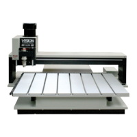
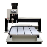
24 Series Engraver Descriptions
(Refer to the Diagrams on the following page)
1. Table Base Plate. This is the large flat plate upon which everything else is mounted. All mechanical
alignments are referenced to this plate, so the space upon which you place the engraving table must be
a reasonably level surface.
Always carry the table by the base plate only. An optional t-slot table may be installed on the table base
plate.
2. X-Axis Linear Rails. Mounted under the table base plate are steel rails with sealed bearings, which
allow the motion of the gantry in the X-axis direction.
3. X-Axis Leadscrews. This are the threaded rods located underneath the table baseplate. Combined
with the stepper motors, the leadscrews are rotated and cause the gantry to move along the rails in the
X-axis direction. There is also a second leadscrew in the Y-axis of the machine. The Y-axis leadscrew is
contained within the gantry and can be accessed by removing the black sheet metal gantry cover. The Y-
axis leadscrew is responsible for motion of the carriage assembly, moving it back and forth across the
gantry.
4. Gantry Assembly. The gantry or “bridge” is a large, rectangular bar suspended across the width of the
table. It travels down the table along the X-axis.
5. Carriage Assembly. The carriage assembly houses the engraving spindle, the Z-axis mechanism and
the engraving motor. The carriage moves along the gantry assembly on a set of sealed bearings in the Y-
axis. The carriage assembly raises and lowers the engraving spindle during the engraving process using
the Z-Axis leadscrew and stepper motor.
6. 25 Pin Connector. This connector port is used to connect the table to the system controller.
7. Y-Axis Stepper Motor. Drives the carriage in the Y-Axis.
8. X-Axis Stepper Motors. Drives the gantry in the X-Axis.
9. Edge Guides. Used as a back and side stop for accurately locating material and clamps during set-
up.
10. Engraving Motor. Drives the spindle for rotary engraving.
11. Serial Connector. This connector port is used to connect the table to the controller.
12. DACS USB Connector. This optional connector is used to connect the DACS Camera System to
your computer.
13. Spindle Cable. This cable connects to the system controller and provides power to the engraving
motor.
 Loading...