Home
Vision
Engraver
5 Series
Page 31
Vision 5 Series - Page 31
98 pages
Manual
To Next Page
To Next Page
To Previous Page
To Previous Page
Loading...
N
e
tw
ork
C
onne
ct
i
on
31
© 20
19 V
i
s
i
on En
grav
i
ng S
y
s
tems
T
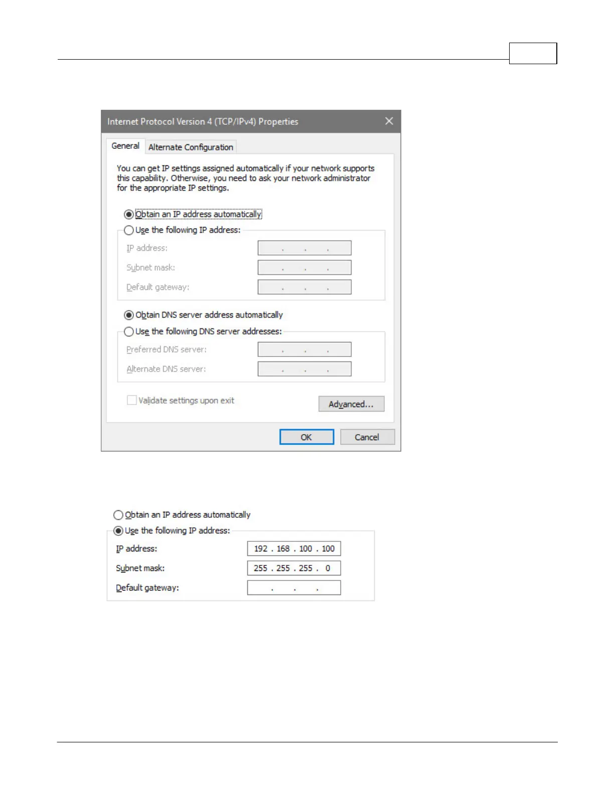
he
s
c
re
en
be
low
will
ap
pe
ar
.
Ent
er
t
he
s
ett
ings
below
.
Selec
t
:
U
s
e
the
fol
l
ow
i
ng
I
P
a
d
dre
s
s
:
Ent
er
an
I
P
add
r
es
s
of
:
19
2.168
.
10
0.100
Ent
er
a S
ub
ne
t
mas
k
of
:
255
.255
.
25
5.0
30
32
Table of Contents
Main Page
Table of Contents
3
Part I Introduction
5
Disclaimer and Warranty Information
5
Part II 1612, 1624, 2424 and 2448 Series
5
Safety Precautions
7
Computer Requirements
10
Vision Software Security Device
10
General Electrical and Facility Requirements
11
Installation
12
Locating the Engraver
12
Installation Layout Diagrams
13
1612 And 1624 Engraver Layout Diagram
13
2424 And 2448 Engraver Layout Diagram
14
Series 5 Controller Connections
23
Pendant Holder Installation
26
Part III Network Connection
28
Part IV Vision Mov UI Software Installation
33
Part V Vision Software Installation
41
Part VI Operation
52
Starting the Vision Mov UI Spooler
52
Pendant Controls
54
Startup Screen
55
Emergency Stop Button
56
Setup Screen
58
Run Screen
60
Set XYZ Screen
65
Job Select Screen
71
Adjust Screen
74
Search Screen
76
Origin Select Screen
79
6.2.10 Surface Location Screen
83
6.2.11 Utilities Screen
84
6.2.12 Diagnostic Screen
85
Set Surface Procedures
85
Set Home Procedure
88
Part VII Sending Jobs to Your Machine
90
Other manuals for Vision 5 Series
Installation Guide
45 pages
Related product manuals
Vision MAX Pro
183 pages
Vision 16 Series
31 pages
Vision 1612
40 pages
Vision VE-810
69 pages
Vision 1624
98 pages
Vision 2448
98 pages
Vision 1624R
69 pages
Vision Phoenix 1212
39 pages