Page 19
Section 6.1.2 Custom Switch Installation
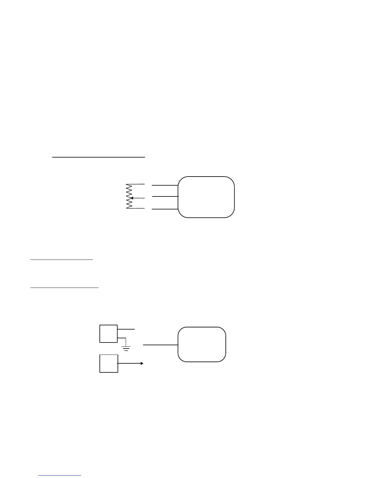
Custom Remote RPM Control requires a potentiometer type input. The potentiometer or other type of resistor
network, is used to adjust the engine speed by providing a voltage between 0.5V and 4.5V to the module. For
remote activation, it is recommended that a Remote FORD switch is installed as described above to activate and
deactivate Custom RPM Control.
Quality UL recognized industrial switches with gold contacts are recommended for contact durability due to the
low current.
Programming is required to use the custom switch.
For information on what engine speed (RPM) value corresponds to what custom input voltage (V), refer to Section
9.
For Remote Custom RPM Control:
Connect potentiometer to red VREF output, black SIG RTN, pink CUSTOM input.
The Custom Input Voltage should sweep between 0 and 5V. A 5-10kΩ potentiometer is recommended.
Section 6.1.3 PTO Control Installation
For 4R100 PTO usage:
Connect the yellow PTO output to the 12V PTO solenoid AND PTO input circuit to the PCM.
Refer to Ford Body Builders Manual for latest Power Take-Off installation information.
For other electrical loads:
Connect the yellow PTO output to an external 12V electrical load.
Refer to Section 9 for specifications for the PTO driver output source.
Yellow
PTO (VBAT)
APCM
PTO Solenoid
- Dana Corp.
- Muncie Inc.
Red
VREF 5V
SIG RTN
Black
APCM
Potentiometer
CUSTOM
Pink
PTO Circuit
- #322 PTO Input
12V
PCM
PTO
 Loading...