Page 23
Section 9.1 CUSTOM INPUT VOLTAGE TO OUTPUT SPEED
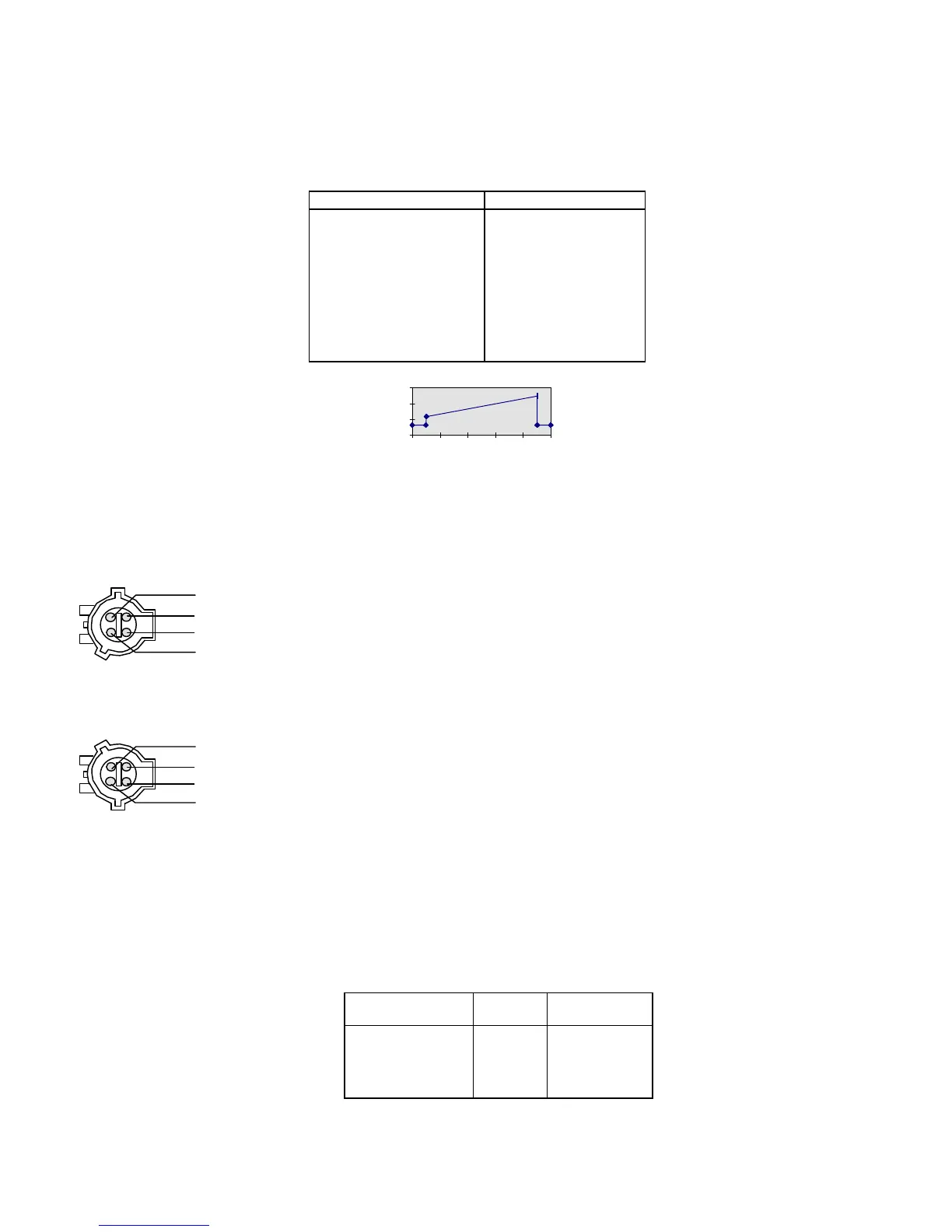
Table 9.1.1: Custom Voltage to RPM Function
Input Voltage (V) Engine Speed (RPM)
<0.5V (normal idle)
0.5V 1200
1.0V 1360
1.5V 1525
2.0V 1685
3.0V 2010
4.5V 2500
>4.5V (normal idle)
V = (RPM - 1037.5) / 325 RPM = 325 x V + 1037.5
RPM VS. VOLTAGE
0
1000
2000
3000
0 1 2 3 4 5
Vin
Section 9.2 APCM MODULE HARNESS CONNECTORS
Vehicle Side: Ford Part No. E8EB-14A464-BZA
KEY POWER F-Series (RED/YELLOW) E-Series (RED/LIGHT GREEN)
Module Side: Ford Part No. F3LB-12624-ZB
Section 9.3 ENGINE SPEED RATE OF CHANGE TABLES
In RPM Control mode, the engine speed is manually adjustable with the [ARROW] keys.
Table 9.3.1 indicates the rate of change in engine speed for the up/down [ARROW] keys. These are not
adjustable.
Table 9.3.1: Manual RPM Rates
[ARROW] key Symbol RPM/second
"Fast" up
∧∧
400
"Slow" up
∧
60
"Slow" down
∨
-60
"Fast" down
∨∨
-400
 Loading...