Page 20
Section 6.2 WIRING HARNESS PIN-OUT TABLE
Connector
Position
Wire Color Signal Description Notes
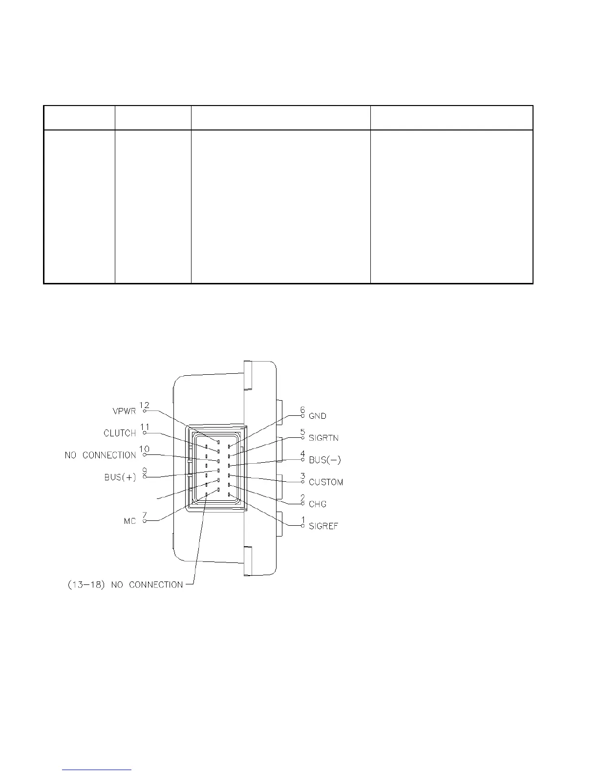
1
Red Signal Reference Voltage 5Vdc Use for source to remote inputs
2
Orange Remote Charge Protection Input Use for Remote CP signal on/off
3
Pink Remote Custom RPM Input Use for Remote RPM signal on/off
4
White/Purple SCP Bus (-) Twisted Pair Connects to Vehicle
5
Black Signal Return Use for Remote Custom Input
6
Black Ground Connects to Vehicle
7
Gray Remote RPM Control Input Use for Remote RPM Input
8
Plugged
9
Red/Blue SCP Bus (+) Twisted Pair Connects to Vehicle
10
Plugged
11
Yellow Power Take-Off Output 12V Source Use for PTO solenoid and EEC
12
Tan/Red Ignition Source Power (VPWR) Connects to Vehicle
13-18
Plugged
Section 6.2.1 18-Pin Connector Pin-Out Diagram
NO CONNECTION
 Loading...