™
Page 49 of 81
6 Loc3-10Tx Transmitter
6.3 Transmitting Modes
The transmitter has three transmitting modes, which are selected automatically.
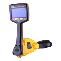
6.3.1 Induction Mode
This uses an internal antenna to induce a locating frequency onto the target pipe or cable (line). “Induction” mode is
automatically selected if no connection accessories are plugged into the “output socket”. An icon indicating “Induction” mode
shows on the display. The icon flashes when the transmitter is transmitting. In order to generate successful induction, the
transmitter should be positioned over and with the handle in line with the target line.
FUSE
“Induction” mode is generally used when no access is available to make a direct connection, or a clamp connection. When
using induction it is very likely that the signal being induced onto the target line will also be induced onto other lines in the
area, and onto above ground features such as wire fences. This can inuence the accuracy of the location, depth and current
measurements. “Induction” mode is also the least ecient way of applying the transmitting signal to the target line. The distance
located with “Induction” mode is generally much less than that achieved with a direct connection or clamp connection. The
“Induction” mode is only available from 8kHz and above.
Induction frequencies are available based on the user selection. See section 6.4.2, for information relating to “Most Used
Frequencies (Frequency Selection) Feature”, for adding and removing frequency from the favorite frequencies list.
NOTE
For accurate location and depth measurement the locator receiver should be used no closer than 66ft
(20m) from the transmitter.
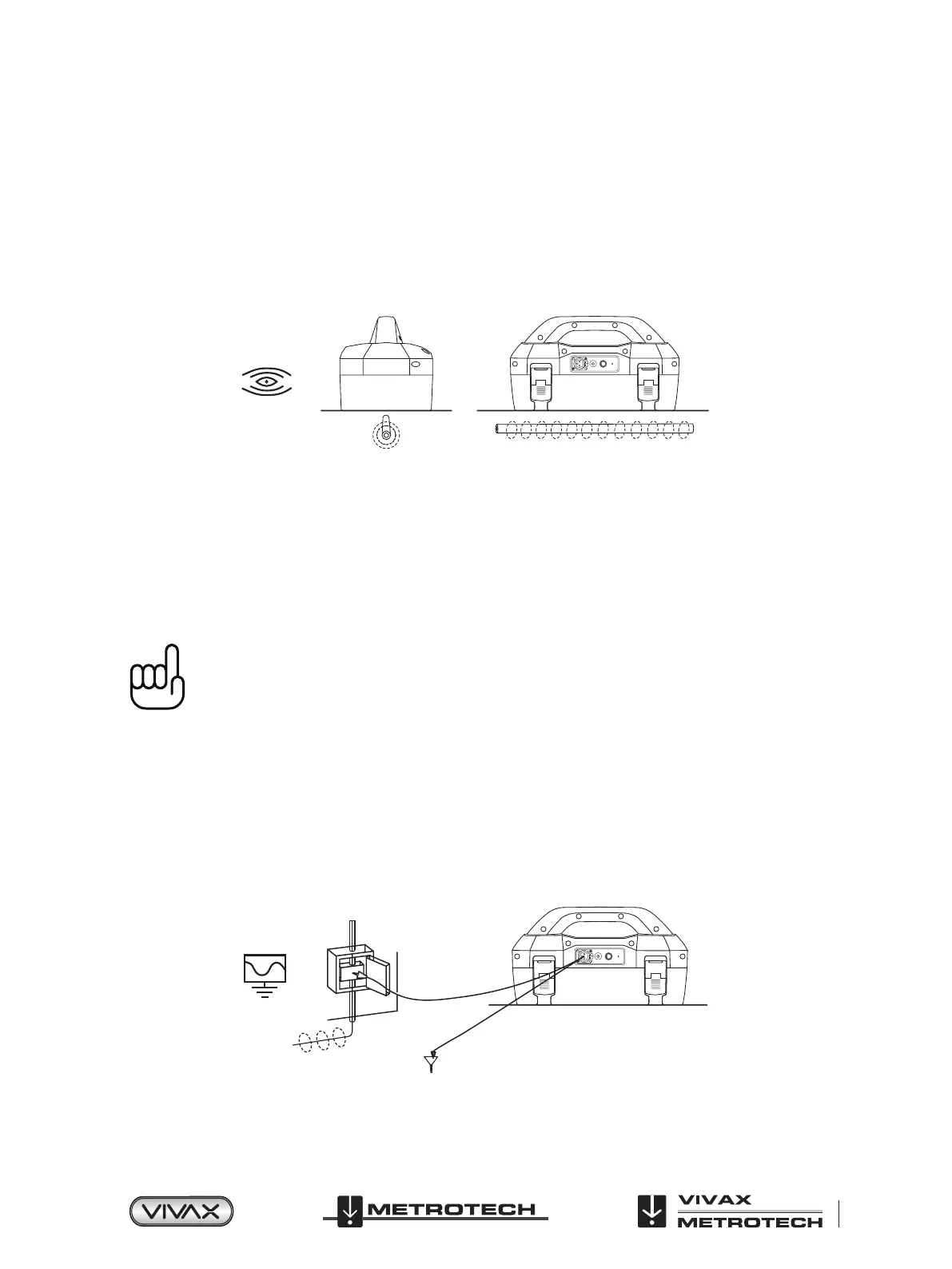
6.3.2 Direct Connection Mode
“Direct Connection” mode is automatically selected by plugging in a connection lead to the output socket. An icon conrming this
is shown on the display. The wave in icon uctuates when the transmitter is transmitting. The direct connection lead consists of
two cables, one (red clip) must be connected to the conductor being located, the other (black clip) to a suitable ground (a ground
stake is provided with the transmitter). A ground extension spool is also supplied. If the ground extension spool is used, the
ground clip of the connection lead (black clip) is attached to one end of the auxiliary ground lead.
A good connection is indicated by a change in beep rate from the speaker and the current reading on the display.
FUSE
Wherever a direct connection can be safely made without the risk of injury, damage to customer’s plant, or the transmitter, it is
the best way of applying the transmitter’s signal.
 Loading...