™
Page 69 of 81
8 Using the Accessories
Fault finding requires a non-standard signal “8kHz FF” (or FF fault find signal but ensure the Rx and Tx settings are matched).
To detect a damaged section, the line should be isolated and have all ground bonding removed. This will ensure that the ground
fault is not masked by deliberate bonding to ground. The A-frame cannot distinguish between these two situations.
After isolating the line, use the transmitter resistance measuring function, or a dedicated resistance measuring device to confirm
that there is a fault to ground. The A-frame will typically detect faults up to 2 Mohm (depending on the distance from transmitter,
soil conditions etc).
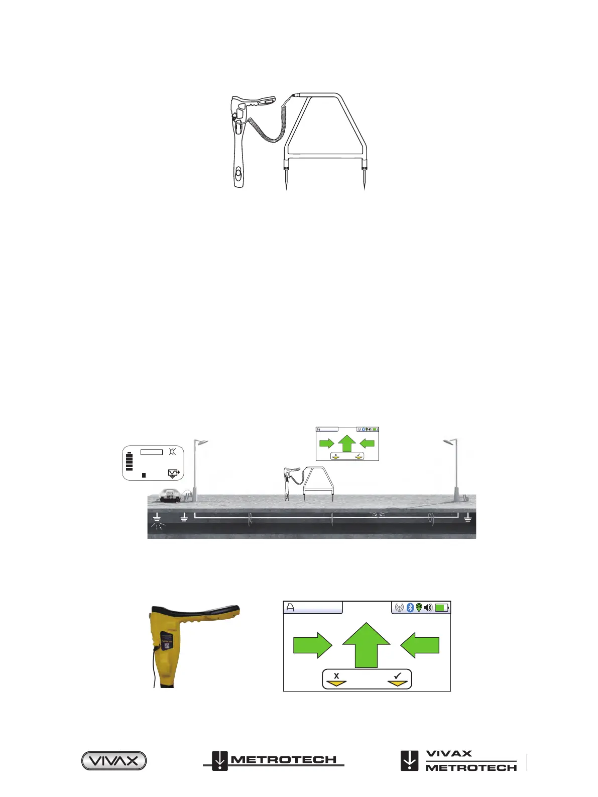
A ground stake needs to be pushed into the ground and the black cable clipped to it. Try to place the ground stake as far as
possible from the line to be evaluated. This ensures return currents do not distort the results.
Always connect the ground stake first when connecting up and last when disconnecting. Make the connections before switching
on as hazardous voltages can be present on the connection clips.
Connect the transmitter to the target line using the red lead. Switch on the transmitter and select either 8kFF low or 8kFF high.
Use 8kFF high if the line to be surveyed is long or the fault resistance is high. Make sure the receiver and transmitter are set for
the same FF type, i.e. 8kFF.
55
8kFF LOW
mA
26 dB
8KFF
Log
6
Plug in the A-frame to the receiver accessory socket. When the receiver is switched on, it will automatically default to the A-frame
screen.
Note also the Auto shutdown setting will be set to “Never shutdown” when the A frame is attached.
8KFF
Log
6
Image for reference only and may differ from actual image
 Loading...