Wiring Diagrams
4
Vivint Element CT200 Installation Guide
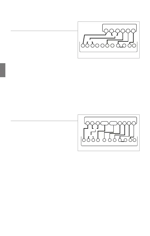
4 Wire Heat Pump (heat/cool)
without Auxiliary Heat
1. Connect the O wire to the O
terminal or the B wire to the
B terminal. This connects the
change-over valve. If you have
both O and B, connect only the
O wire to the O terminal and DO
NOT connect B to B terminal (see the Wire Reference Table on
page 23 for Trane terminal labels).
2. Connect the Y wire to the Y terminal. This connects the
compressor.
3. Connect the R wire to the RH terminal. This connects the power.
4. Connect the G wire to the G terminal. This connects the fan.
5. If available, connect the C wire to the C terminal.
6. Go to “Connect Your Wires” on page 9.
Multi-stage Heat Pump with
Multi-Stage Aux Heat
The CT200 can handle up to 2
stages of Pump compression and 2
stages of AUX heat.
1. Connect O wire to the O terminal
or the B wire to the B terminal.
This connects the change-over
valve. If you have both O and B,
connect only the O wire to the O terminal and DO NOT connect
B to B terminal (see Wire Reference Table on page X for Trane
terminal labels.).
2. Connect the AUX 1 and AUX 2 wires to the AUX 1 and AUX 2
terminals. This connects the auxiliary heat.
3. Connect the Y and Y2 wires to the Y and Y2 terminals. This
connects the compressor.
4. Connect the R wire to RH terminal. This connects the power.
5. Connect the G wire to the G terminal. This connects the fan.
6. If available, connect the C wire to the C terminal.
7. Go to “Connect Your Wires” on page 9.
POWER
HVAC SYSTEM
THERMOSTAT TERMINALS
CB OW YY2
RH
RC GAW2
B
G
O
Y R
C
or
or
POWER
HVAC SYSTEM
THERMOSTAT TERMINALS
CBOW YY2
RH
RC GAW2
B
G
O
Y R
C
or
or
Y2AUX2AUX1
26