VIVOTEK - A Leading Provider of Multimedia Communication Solutions
User's Manual - 5
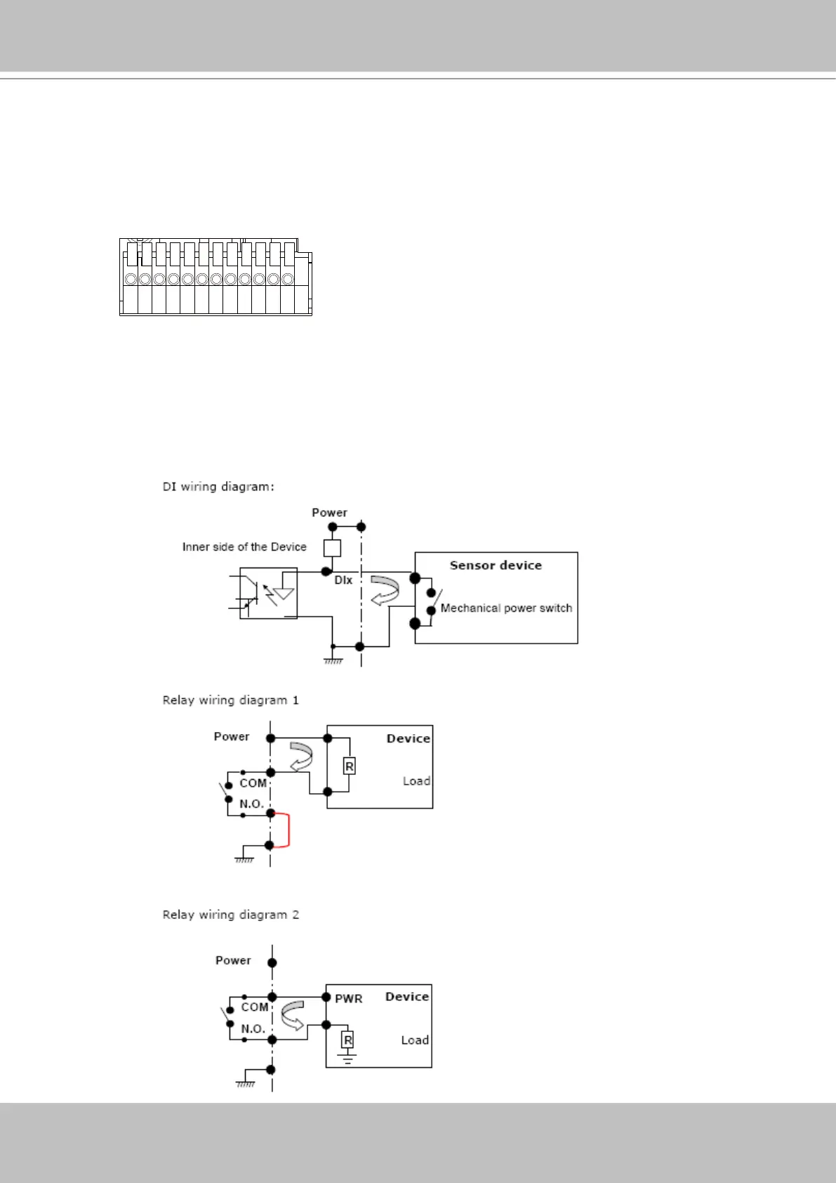
1 2 3 4 5 6 7 8 9 10 11 12
1: Power
2: Relay output COM
3: Relay output N.O.
4: Digital Input 1
5: Digital Input 1 Ground
6: Digital Input 2
7: Digital Input 2 Ground
8: Digital Input 3
9: Digital Input 3 Ground
10: Digital Input 4
11: Digital Input 4 Ground
12: Ground
General I/O Terminal Block
This Network Camera provides a general I/O terminal block which is used to connect external
input / output devices. The pin denitions are described below.
DI/DO Diagram
Refer to the following illustration for connection method.