VIVOTEK - A Leading Provider of Multimedia Communication Solutions
User's Manual - 9
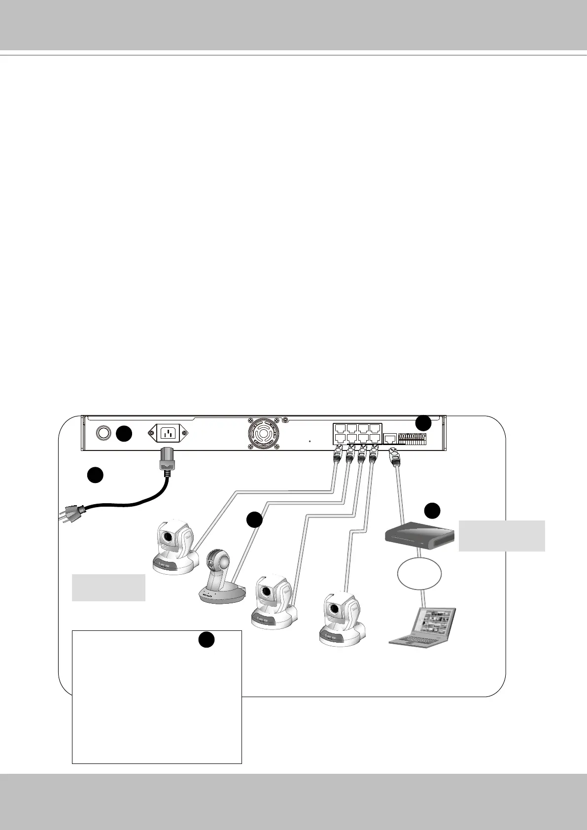
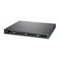
Network deployment
Device Connection
1. Connect the supplied power cable from the NR8201/8301 to a power outlet.
2. Press the power button to power up.
3. Connect network cameras to NR8201/8301 LAN ports.
Because NR8201/8301
supports PoE, if the Network Camera is PoE-compliant (802.3af), an
Ethernet cable transmits both power and data.
4. 4-1. If your local network does not have a DHCP server, you may temporarily connect a PC
to an NVR’s LAN port for initial setup. The NVR comes with a default IP, 192.168.100.1. You
may access the NVR server using this IP, and then manually assign an IP to the NVR WAN
port.
4-2. If your local network has a DHCP server, connect the WAN port to your local network,
and use the IW2 utility to nd the NVR server IP. You may then access the NVR server by en-
tering the discovered IP in the address eld of a web browser.
5. If you have external devices such as sensors and alarms, make connections from general I/O
terminal block.
1 234 5 6 7 8 9 101112
WAN
POWER AC IN 100V-240V
LAN8
LAN7
LAN6
LAN5
LAN4
LAN3
LAN2
LAN1
RESET
LAN
LAN/WAN
Activity
Power/MIC
Activity
Power/MIC
Activity
Power/MIC
Internet
DSL Modem
Router
1
2
Network Camera
(w/ or w/o PoE)
3
5
Cable, DSL
Modem, or router
1: Power
2: Relay output COM
3: Relay output N.O.
4: Digital Input 1
5: Digital Input 1 Ground
6: Digital Input 2
7: Digital Input 2 Ground
8: Digital Input 3
9: Digital Input 3 Ground
10: Digital Input 4
11: Digital Input 4 Ground
12: Ground
5
4