Installation and Operating Manual / Version 10 / 3626-011500
en
/ Protection class 0: public / 2017-12-15
BTS, non-contacting thermal switch unit
-compliance with mounting instructions.
Ensure that the bracket is of sufficient stability (not included in Voith's scope
of supply)!
It is vital to avoid any vibrations as false signals might occur!
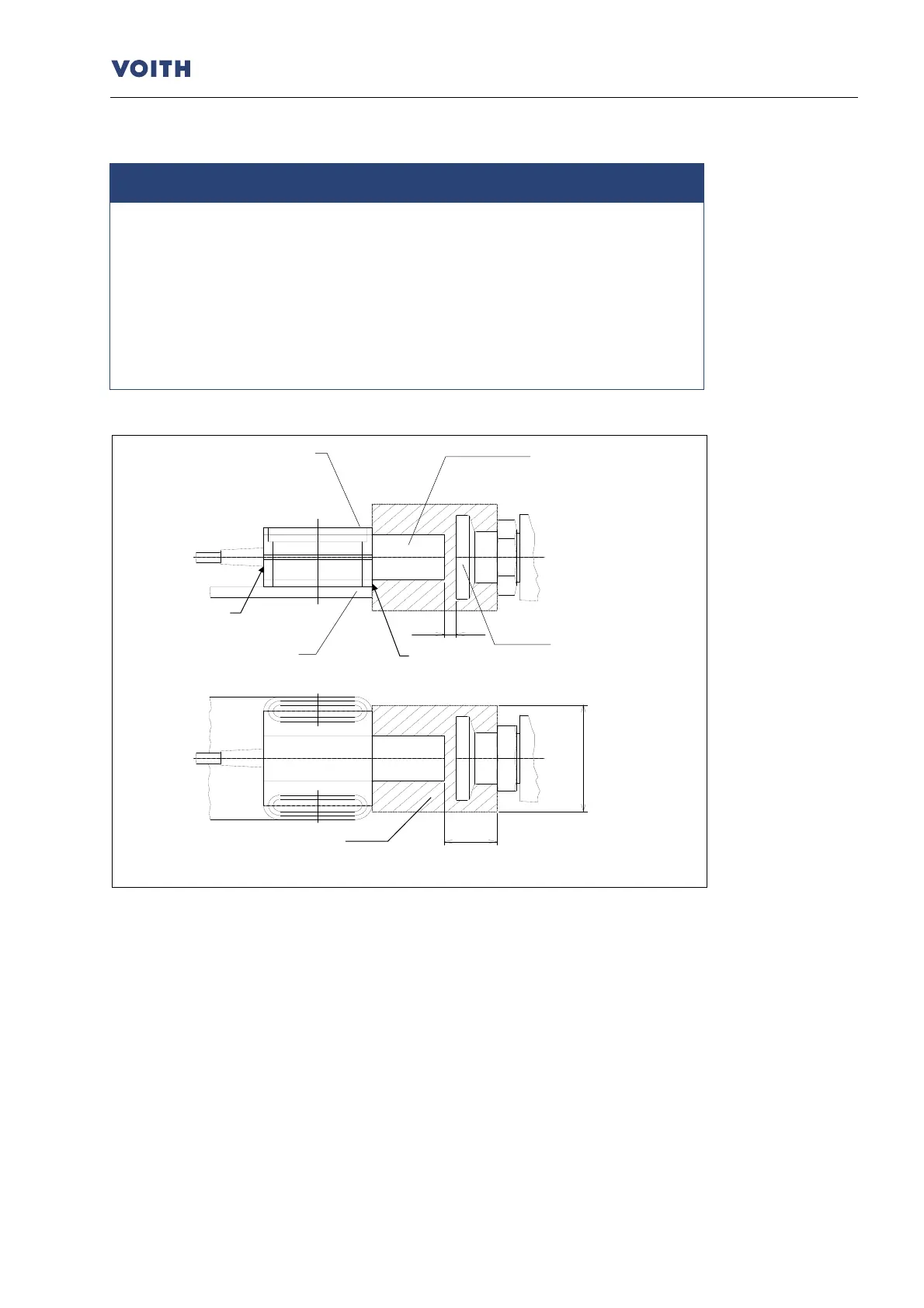
Observe the metal-free area (15 mm) around the initiator head (
Fig. 7
•
Mount the initiator with mounting flange on the pitch circle diameter of the
switching element and on a bracket, in parallel with the turbo coupling axis.
•
Mount the initiator end flush with the mounting flange. Mount the mounting flange
front flush with the bracket.
•
Set the distance between initiator head and switching element to 4 ± 1 mm!