Installation and Operating Manual / Version 10 / 3626-011500
en
/ Protection class 0: public / 2017-12-15
BTS, non-contacting thermal switch unit
The correlation between switching element and fusible plug may vary dependent on
the project design. Differing nominal response temperatures of the switching element
(85°C, 90°C, 100°C, 110°C, 125°C, 140°C, 160°C and 180°C) are also available
(Chapter 13).
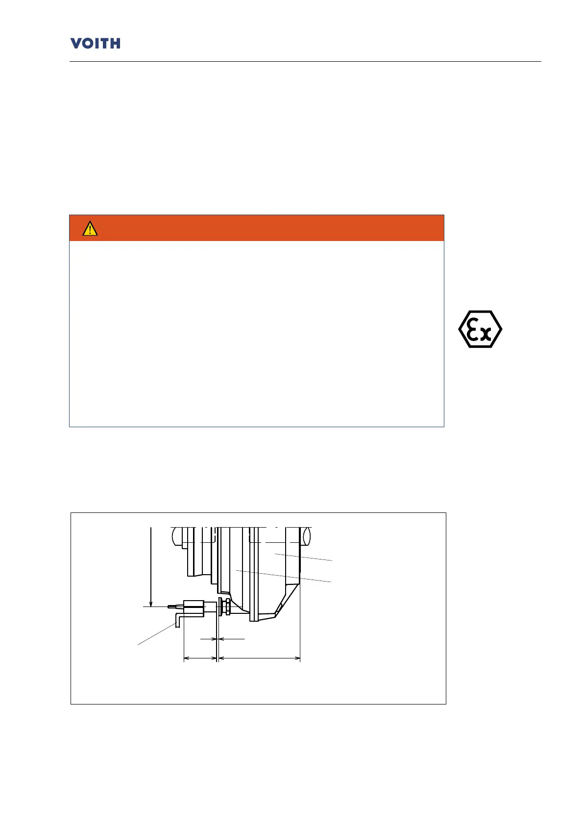
6.3 Mounting - switching element and initiator
-compliance with mounting instructions.
To avoid any damages, switching element and initiator should be mounted
after installation and prior to filling the turbo coupling.
Equipment which is operated in potentially explosive atmospheres must not
be modified.
It is not possible to carry out repairs on such equipment.
Avoid any impact effects on the initiator. Working on the machine is permitted
only in non-explosive atmospheres.
In order to prevent electrostatic charging, lay the connecting lines in
accordance with EN 50281-1-2 and ensure tha
t chafing during operation is
not possible.
•
Replace the blind screw by the switching element with the sealing ring in the turbo
coupling outer wheel (item 0300) or shell (item 0190)
1)
.
Arrangement of switching element on the outer wheel side
2)
:
Fig. 4
1) Not for turbo couplings of type DT.
2) For turbo couplings of type DT, installation is also possible on the opposite outer wheel side.
Turbo