– Remove dash panel trim on driver side ⇒ General body re‐
pairs, interior; Rep. gr. 68 ; Compartments/covers; Removing
and installing dash panel trim on driver side .
– Remove lower A-pillar trim on driver side ⇒ General body re‐
pairs, interior; Rep. gr. 70 ; Trims, interior; Removing and
installing A-pillar trim .
Note
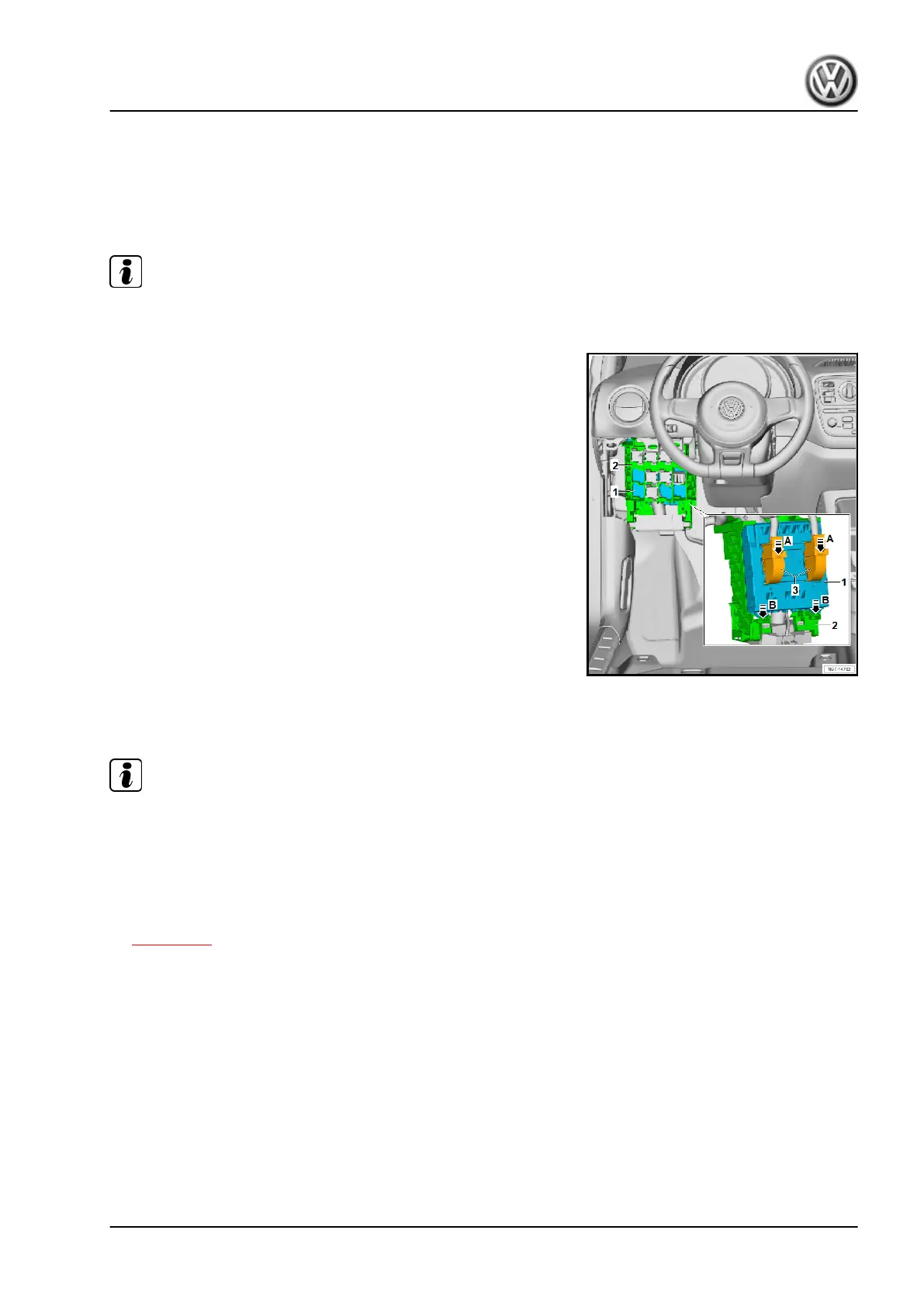
The following illustration shows the installed onboard supply con‐
trol unit on the rear of the relay carrier.
– Swing down the two tabs of primary locking element -3- in di‐
rection of -arrow A-, and pull the two connectors off onboard
supply control unit - J519- -1-.
– Release retaining springs of bracket -2- in direction of
-arrow B-, swing out onboard supply control unit - J519- -1-,
and remove it downwards.
Installing
Install in the reverse order of removal, observing the following:
– First insert onboard supply control unit - J519- -1- into upper
mountings on bracket, and then clip it into lower fasteners of
bracket -2- until it engages audibly.
2.2 Removing and installing data bus diag‐
nostic interface - J533-
Note
♦
The data bus diagnostic interface - J533- is integrated into the
onboard supply control unit - J519- and cannot be renewed
individually.
♦
If it is defective, the onboard supply control unit - J519- must
be renewed.
– Removing and installing onboard supply control unit - J519-
⇒ page 154 .
up! 2017 ➤ , up! 2020 ➤
Electrical system - Edition 10.2019
2. Control units 155
 Loading...