74
PREREGLAGES (SETUP)8.
Dans le menu Setup, différents paramètres peuvent être prédéfi nis.
En appuyant longtemps sur la touche SETUP, vous accédez au menu Setup. En appuyant de nouveau
sur la touche SETUP, vous accédez au sous-menu suivant.
Les touches “MAXMIN” et “REL +” font varier le paramètre vers le bas (-) ou vers le haut (+) après chaque
pression de touche.
Les touches “STORE” et “HOLD” décalent la décimale vers l’avant ou vers l’arrière.
Le menu Setup est structuré selon la séquence suivante :
LOW Réglage de la valeur limite pour le niveau inférieur ; en cas de dépassement, un signal
sonore retentit. Préréglage = LOW (Arrêt) valeur max. -40 000 ; Pour réinitialiser, appuyer
sur la touche “STORE” (OFF)
HIGH Réglage de la valeur limite pour le niveau inférieur; en cas de dépassement, un signal
sonore retentit. Préréglage = OFF (Arrêt)
Préréglage = LOW (Arrêt) Valeur max. 40000 ; Pour réinitialiser, appuyer sur la touche
“STORE” (OFF)
Réglage Auto-Power-OFF en minutes :
10 / 20 / 30 / OFF. Préréglage = 10 minutes
Réglage du signal sonore en cas d’essai de continuité :
1 = signal sonore long et affi chage de symbole
OFF = pas de signal sonore, le symbole clignote; Préréglage = 1
Réglage du temps de mise hors circuit de l’éclairage de l’écran en secondes
10 / 20 / 30 / OFF (Arrêt); Préréglage = 10
“Bargraph” Modifi cation de la représentation graphique à barres
1 = Le point zéro est situé au milieu (uniquement pour DC et température)
2 = Le point zéro est situé sur le bord gauche
Préréglage = 1
Pour sauvegarder les réglages, chaque modifi cation de paramètre doit être confi rmée en
appuyant sur la touche „EXIT“ ! Plusieurs paramètres peuvent être sauvegardés les uns
avec les autres.
47
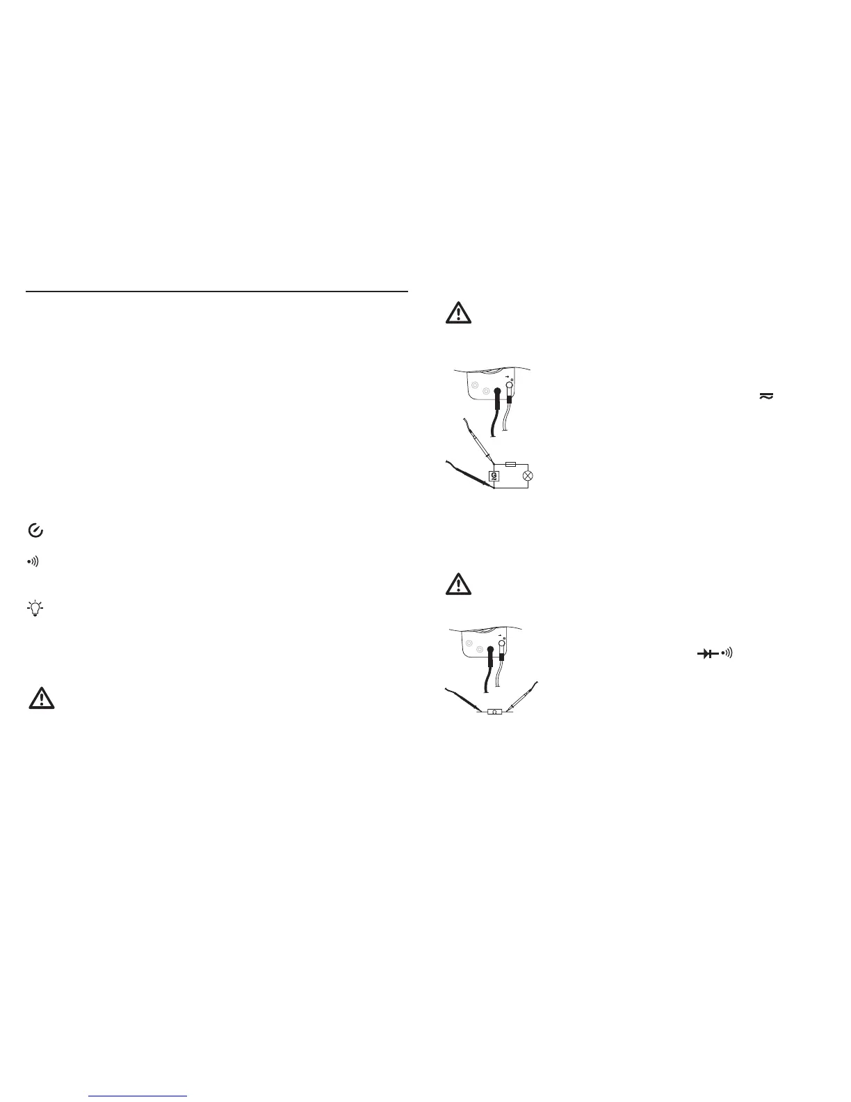
b) AC voltage measurement
(True-RMS)
Never exceed the max. allowable input values, even when measuring superimposed
DC voltages (e.g., ripple voltages). Max. 750 VACrms. Do not touch circuits or parts of
circuits if there could be voltages higher than 25 VACrms or 35 VDC in them.
Proceed as follows to measure AC voltages:
10 A MAX
μAmA COM
HzV
°C
G
~
Connect the black test lead to the COM jack and the red test lead to the •
VΩ jack so that they are lying fl at on the measuring device.
Set the range selector switch (5) to “V~” (for VC940: “V • ”).
For the VC940, switch to AC voltage measurement by pressing the blue •
button. “AC True RMS” appears on the display.
Now connect the two probe tips to the measurement object (generator, •
circuit, etc.).
The measured value is shown on the main display (12). The frequency •
of the AC voltage is shown on the right subdisplay. The active measuring
range is shown on the left subdisplay.
The AC voltage measuring range “V AC” exhibits an input resistance of approx. 10 MΩ.
Press the yellow “AC+DC” push button to switch to coupled AC and DC true RMS measurement. “AC+DC
True RMS” appears on the display (1).
c) Resistance measurement
Make sure that all circuit parts, circuits, and components as well as other objects to be
measured are deenergized at all times.
Proceed as follows to measure resistance and for the acoustic continuity test:
10 A MAX
μAmA% COM
HzV
°C
Connect the black test lead to the COM jack and the red test lead to the •
VΩ jack so that they are lying fl at on the measuring device.
Set the range selector switch (5) to “Ω • ”.
Check the continuity of the test leads by touching the probe tips together. •
This should produce a resistance of approx. 0 Ω.
Now connect the probe tips to the measurement object. The measured •
value is shown on the main display (12) if the measurement object does
not have a high resistance or a broken circuit. The active measuring range
is shown on the left subdisplay.
Note!
When performing a resistance measurement, ensure that the measurement points that you touch the
probe tips to for making the measurement are free of dirt, oil, solder paint, and similar contaminants. An
incorrect measurement may result under such circumstances.
If “OL” (for overload) appears on the display, your measurement is above the measuring range
or the measurement circuit is broken.
 Loading...