48
d) Acoustic continuity test
Proceed as follows to perform this measurement:
Plug the test leads into the measuring device as described in section c above (“Resistance •
measurement”).
Set the range selector switch (5) to “Ω • ”.
Press the blue button to switch to the acoustic continuity test range. “ ” appears. The measured value is •
shown on the main display (12). Continuity is detected for measured values of < 50 Ω; a beep sounds.
The beep function can be deactivated in the setup menu.
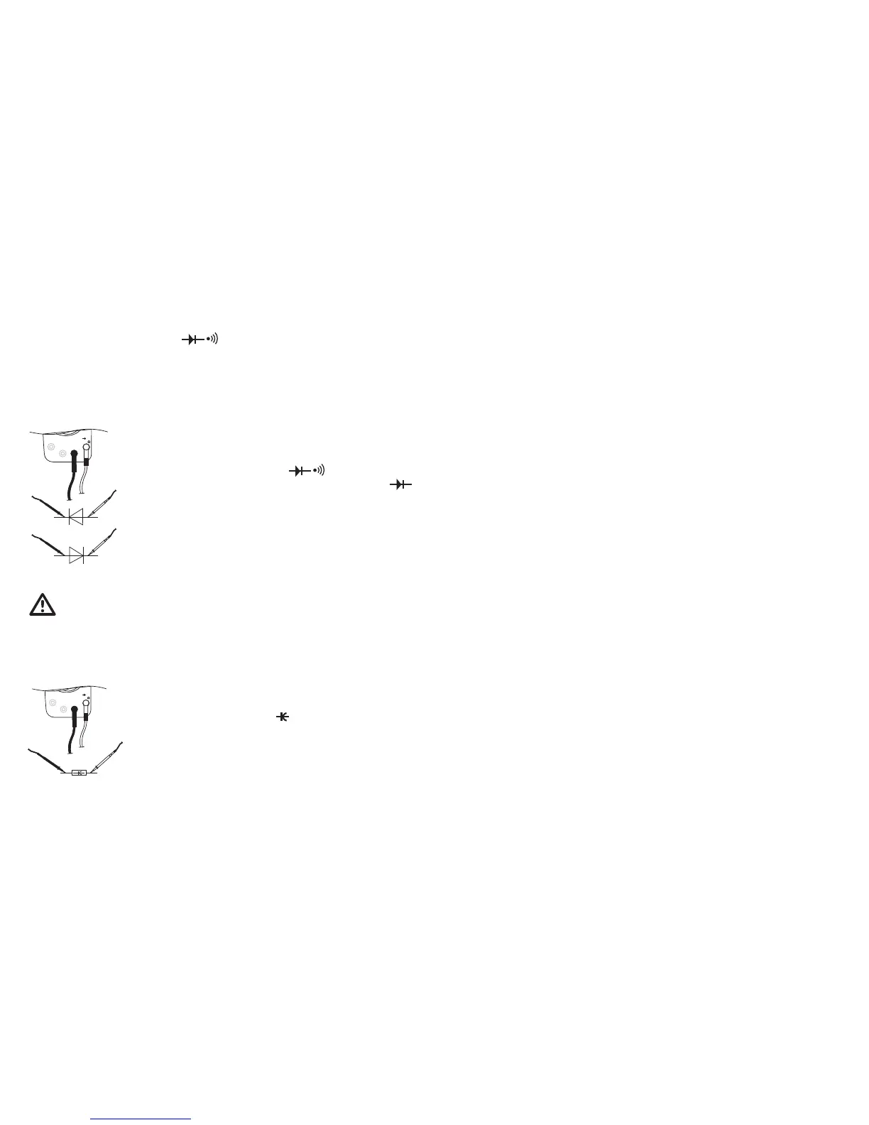
e) Diode test
Proceed as follows to perform this measurement:
10 A MAX
μAmA% COM
HzV
°C
Plug the test leads into the measuring device as described in section c •
above (“Resistance measurement”).
Set the range selector switch (5) to “Ω • ”.
Press the blue button twice to switch to the diode test range. “ • ”
appears on the display.
Check the continuity of the test leads by touching the probe tips together. •
This should produce a value of approx. 0.
Now connect the probe tips to the measurement object (diode). In the •
forward bias direction, the voltage is shown on the main display (12).
f) Capacitance measurement
Never exceed the maximum allowable input values. Discharge each capacitor before
connecting it to the measuring device. If capacitors are short-circuited, high-energy
discharges can result. Do not touch circuits or parts of circuits if there could be voltages
higher than 25 VACrms or 35 VDC in them. Never perform measurements on capacitors
that are installed in circuits or circuit components.
Proceed as follows to measure the capacity of capacitors:
10 A MAX
μAmA% COM
HzV
°C
Connect the black test lead to the COM jack and the red test lead to the •
VΩ jack so that they are lying fl at on the measuring device.
Set the range selector switch (5) to “• ”.
Now connect the probe tips to the measurement object (capacitor). Ensure •
correct polarity (“+” and “-”) of unipolar (poled) capacitors.
The measured value is shown on the main display (12). The active •
measuring range is shown on the left subdisplay.
Note!
Please note that the multimeter needs approx. 2-3 seconds to stabilize the display.
73
REL / +
Mode normal (brève confi rmation) :•
Mesure de la valeur de référence. La sous-partie gauche de l’écran
indique la valeur de mesure effective, la sous-partie droite de l’écran la
valeur de référence et sur l’écran principal, la valeur calculée à partir de
la valeur de mesure effective est indiquée dans la valeur de référence.
En mode RECALL :
Lecture du prochain espace mémoire
En mode STORE :
Augmente l’intervalle de mesure automatique d’une seconde (S) à
chaque pression de touche
Fonction setup (brève confi rmation) :•
Augmente le paramètre actuel
Interrupteur jaune
CA+CC
Mode normal (brève confi rmation) :•
Commute dans les plages de mesure CA vers la fonction couplée
CA+CC TrueRMS. Attention ! Interrupteur qui reste en position.
Touche bleue
Mode normal (brève confi rmation) :•
Commute vers les fonctions de mesure bleues.
Réactivation du multimètre à partir de la fonction Auto-Power-Off
 Loading...