Electrical system
82
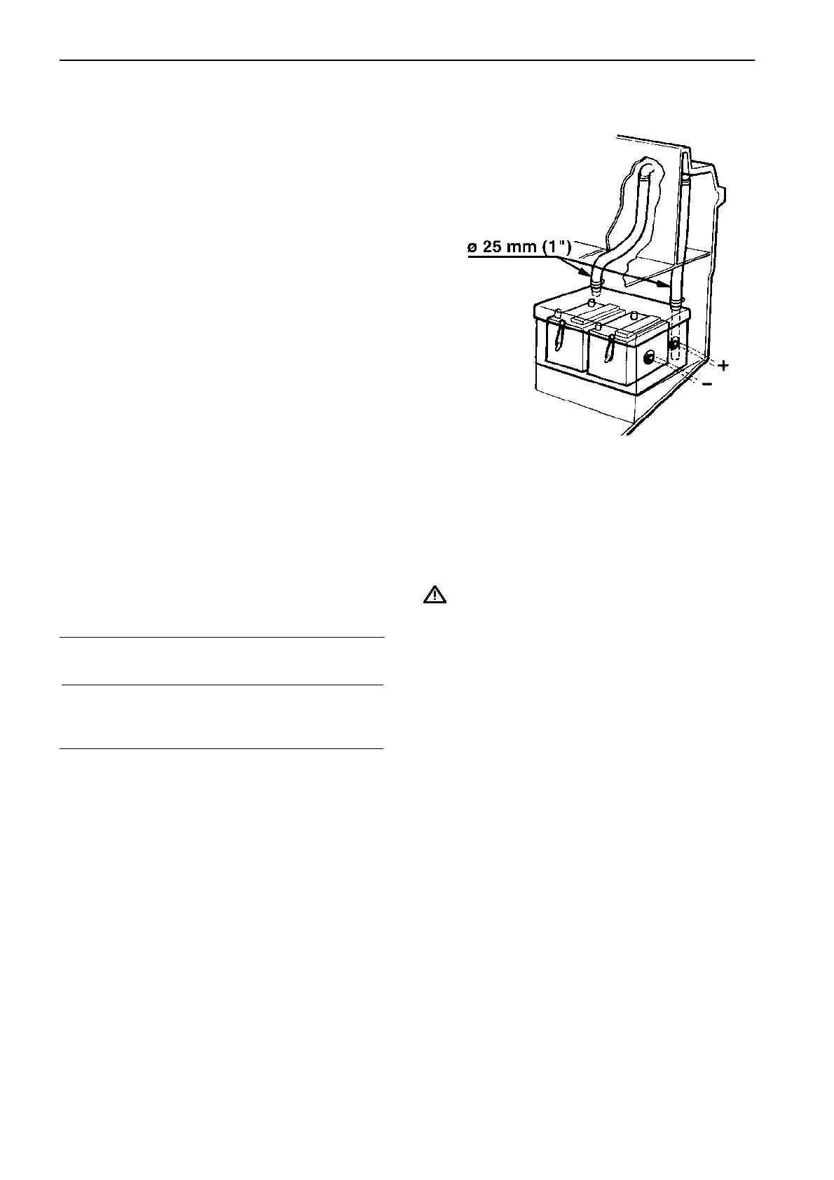
Battery installation
Install the batteries in a tight-fitting box. Vent the box
with 25 mm (1") hoses. The ventilation hose must end
up outside the boat to allow the detonating gas, pro-
duced by batteries, to escape.
The batteries should be fastened and only allowed to
move max 10 mm (3/8").
WARNING! The batteries, if they are not the
closed type, may only be installed in the engine
compartment if they are installed in a separate
sealed and well ventilated battery box. Battery
gas is easily ignited and highly volatile. Sparks
or open flames can cause explosion or fire.
Battery size
Cranking current
Cold cranking current for engines at –5°C (23°F)
12V system:
31-44 series 450A
KAMD300 450A
24V system:
TAMD41 250A
As a guideline the breakaway current can be calculat-
ed as 2–2.5 times cranking current.
Battery size
When selecting battery size, it is vital to look at both
momentary and long-term capacity.
The rating norm for long-term capacity (batteries
marked with Ah) the C20 norm is used.
C20 means the amount of current able to take out
from the battery during 20 h.
Ex. 1: 60Ah = 20 h X 3A
Ex 2: 100Ah = 20 h X 5A
The battery sizes listed below are recommended for
Volvo Penta engines at a temperature down to –5°C
(23°F), SAE norm/700A. Battery voltage is 12V and
24V (TAMD41).
Engine V Capacity, Ah
min max
31-44 series 12V 88 140
KAMD 300 12V 88 140
TAMD41 24V 2x60 2x88
The battery capacity will decrease with approximately
1% / degree Celsius, from +20°C (68°F), which has to
be considered at extreme conditions in temperature.