Electrical system
83
Battery cable area
To achieve sufficient power from the battery to the
starter motor Volvo Penta recommends cable areas
as below.
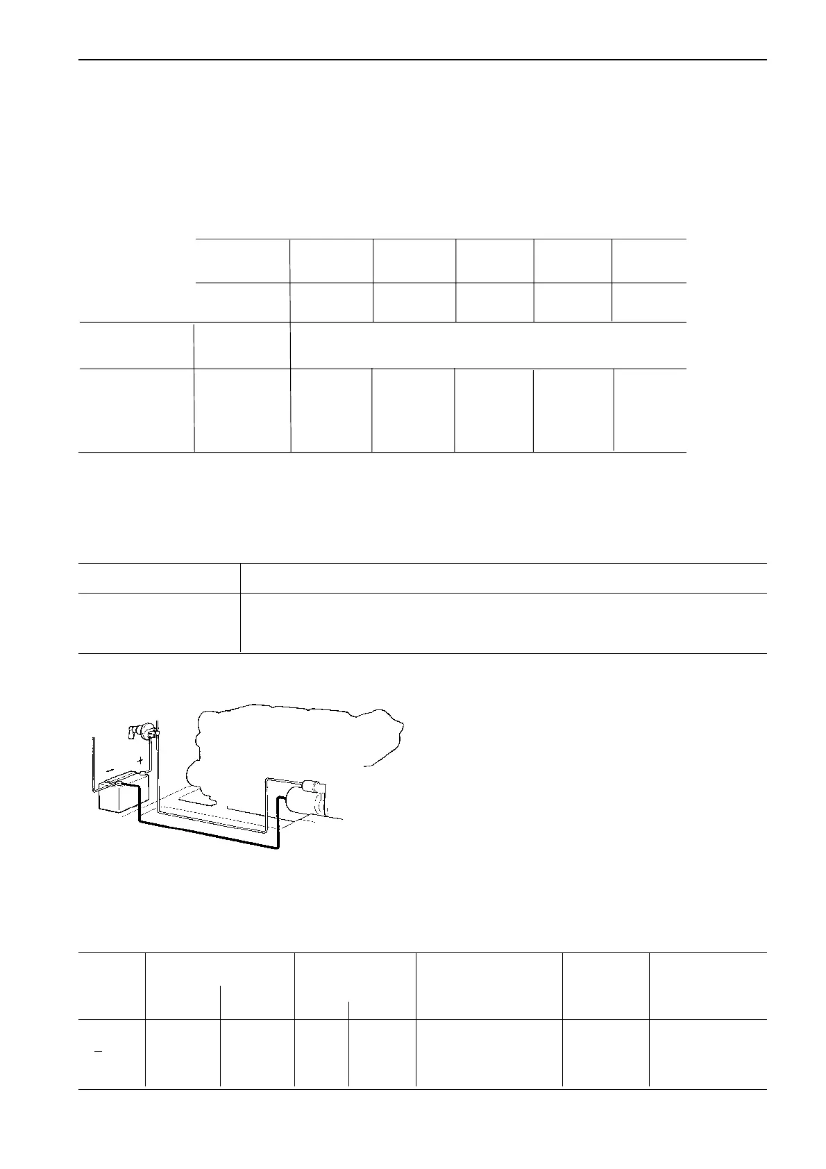
Measure the total cable length from the battery plus
(+) terminal to the starter motor plus (+) terminal and
from the starter motor minus (–) terminal back to the
battery minus (–) terminal .
Thereafter select the recommanded cable area ac-
cording to the table below for both the negative (–) ca-
ble and the positve (+) cable.
Main switch
A main battery switch should be installed on the plus
side. The lead of the positive and negative cables
must be provided with grommets. Position the main
switch outside the engine room but as close to the en-
gine as possible to reduce cable length.
Comparison cable area mm²/ diameter mm according to Volvo standard
Area, mm² 25 35 50 70 95 120
Core diameter, mm 8.6 10.4 11.7 13.8 15.8 17.8
Cable diameter, mm 10.8 12.8 14.5 16.6 19.0 21.0
–
+
Requirements, main switch
Normal Nominal capacity Working T°C/°F Dimension Standard Protection
voltage Contin- During and storage terminal spade tags degree CEI529
uous 5 sec. Min. Max. standard
<48V 150A 1000A –40°C +85°C M10 SAE Marine IP 66
–40°F +185°F J1711
Cable area
mm² 35 50 70 95 120
Cable area
AWG
1
1 AWG 1/0 AWG 2/0 AWG 3/0 AWG 4/0 AWG
Engine Electrical Cable length max
system m (ft)
All engines,
31–44 series 12V 4.0 (13) 5.5 (18) 7.5 (24) 10.0 (33) 12.5 (41)
KAMD300
TAMD41 24V 12.5 (41) 18.0 (59) 25.0 (82) 35.0 (114) 43.0 (141)
1
) AWG (American Wire Gauge)