Standard STD 101-0001
Volvo Group
Version
4
Page
7
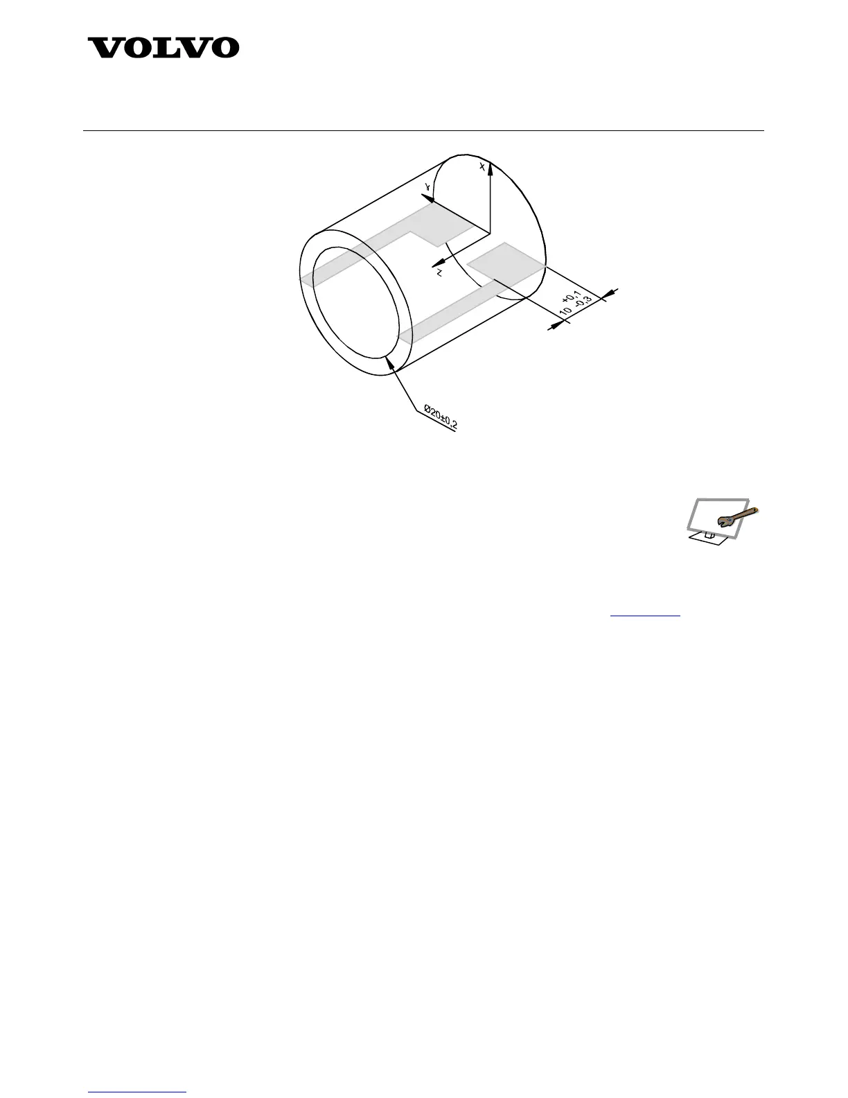
Figure 5 – Showing internal features without using a section
4.1.2 Associativity
The ability to associate digital elements shall be available and maintained. Associativity
information shall be electronically accessible.
4.1.3 Model coordinate systems
A DSM shall contain one or more model coordinate systems. For further information regarding model coordinate
systems, see ISO 16792:2006. Concerning coordinate systems for heavy vehicles, see
STD 5026,1.
4.1.4 Applications of supplemental geometry
When supplemental geometry is used, there shall be a clear distinction between the supplemental geometry and
the model geometry.
a) Represented line element
The following geometric tolerances may use a represented line element to clarify the direction of a two-
dimensional tolerance zone of parallel lines. When a represented line element is used to indicate the
direction of a geometric tolerance application, the leader from the tolerance indicator shall terminate on
the represented line element in an arrowhead, see figure 6a. The following geometric tolerances may use
a represented line element to clarify the directionality of a two-dimensional tolerance zone of parallel lines:
• Straightness applied to the line elements of a planar surface.
• Orientation tolerance applied on each line element on a surface.
• Profile any line. See figure 6a.