In some applications, one group PID parameter is not enough, different PID parameters would be adopted
according to the situation.
The function codes are used to switch two groups PID parameter. The setting mode of the regulator
parameters P40.20~P40.22 is similar as P40.17~P40.19’s.
Two groups PID parameter can be switched via DI terminal, or switched according to PID deviation
automatically.
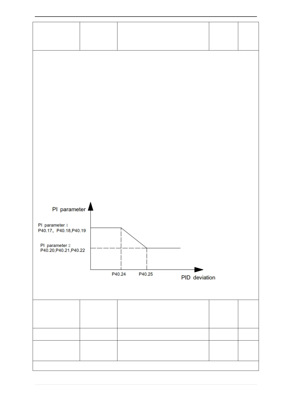
When selection is automatic switching: when the deviation absolute value between given and feedback is
smaller than P40.24 (PID parameter switching deviation 1), PID parameter selection is group 1. When the
deviation absolute value between given and feedback is bigger than P40.25 (PID parameter switching
deviation 2), PID parameter selection is group 2. When the deviation absolute value between given and
feedback is between P40.24 and P40.25, PID parameter is the linear interpolation of two groups PID
parameter, showed as below
parameter switching diagram


 To Next Page